Package Contents
 |
|---|
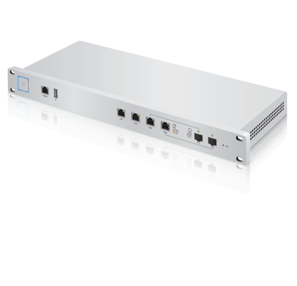
| UniFi Security Gateway Pro |
 |
|---|
| Power Cord |
 |
|---|
| Mounting Screws (Qty. 4) |
 |
|---|
| Cage Nuts (Qty. 4) |
Installation Requirements
- Phillips screwdriver
- Standard-sized, 19” wide rack with a minimum of 1U height available
- For indoor applications, use Category 5 (or above) UTP cabling approved for indoor use.
- For outdoor applications, shielded Category 5 (or above) cabling should be used for all wired Ethernet connections and should be grounded through the AC ground of the power supply.
We recommend that you protect your networks from harmful outdoor environments and destructive ESD events with industrial-grade, shielded Ethernet cable from Ubiquiti. For more details, visit: ui.com/toughcable
|
|
Note: Although the cabling can be located outdoors, the UniFi Gateway itself should be housed inside a protective enclosure. |
|---|

|
|
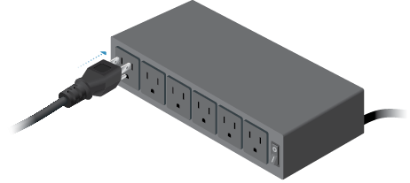
IMPORTANT: We strongly recommend using UPS backup and power regulation to prevent equipment damage due to stability issues with local AC power. |
|---|

System Requirements
- Linux, Mac OS X, or Microsoft Windows 7/8/10
- Java Runtime Environment 1.6 (or above)
- Web Browser: Google Chrome (Other browsers may have limited functionality)
- UniFi Network Application v4.8 or higher (available at: ui.com/download/unifi)
Hardware Overview
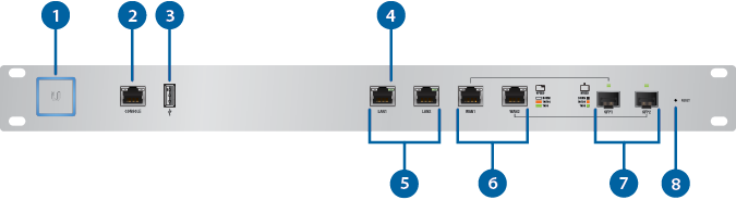

System LED |
|
|---|---|
Click here for detailed descriptions. |
|

Console Port |
|
RJ45 serial console port for Command Line Interface (CLI) management. Use an RJ45-to-DB9 serial console cable, also known as a rollover cable, to connect the Console port to your computer. Then configure the following settings as needed:
|
|

USB Port |
|
Reserved for future use. |
|

LAN / WAN / SFP Speed/Link/Act LED |
|
|
Off |
No Link |
|
Amber |
Link Established at 10/100 Mbps Flashing Indicates Activity |
|
Green |
Link Established at 1000 Mbps Flashing Indicates Activity |

LAN (Ports 1 - 2) |
|
RJ45 ports support 10/100/1000 Ethernet connections. By default, the LAN1 port is set to DHCP Server, and its IP address is 192.168.1.1/24. |
|

WAN (Ports 1 - 2) |
|
RJ45 ports support 10/100/1000 Ethernet connections. A WAN port is active only if the corresponding SFP port is empty. By default, the WAN1 port is set to DHCP Client. |
|

SFP (Ports 1 - 2) |
|
SFP ports are hot-swappable and support 10/100/1000 fiber SFP modules. If an SFP module is plugged in, then the SFP port is active, and the corresponding WAN port is deactivated. By default, the SFP1 port is set to DHCP Client. |
|

Reset Button |
|
Resets to factory defaults. The UniFi Gateway should be running after bootup is complete. Press and hold the Reset button for about 10 seconds until the right LED on the WAN2 port starts flashing and then becomes solidly lit. After a few seconds, the LED will turn off, and the UniFi Gateway will automatically reboot. |
|
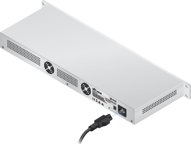
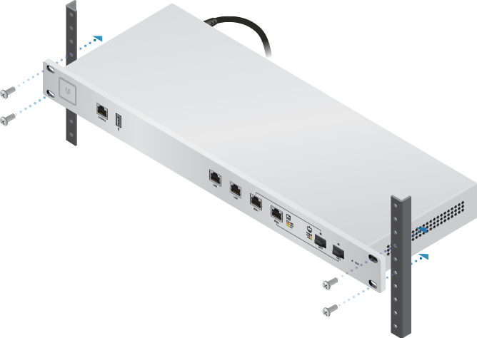
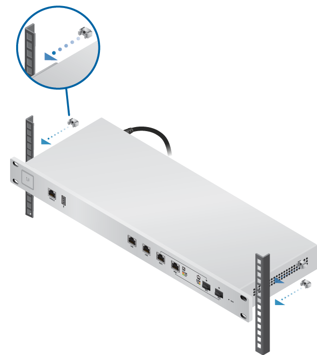
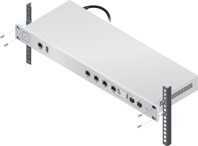
Hardware Installation
OR
Connecting Ethernet
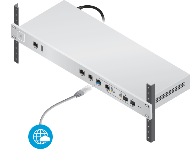
Using SFP Ports
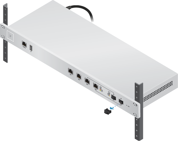
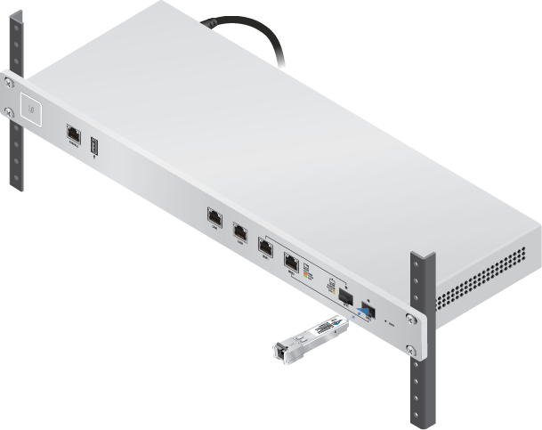
| Note: The corresponding WAN port will be deactivated. |
|---|
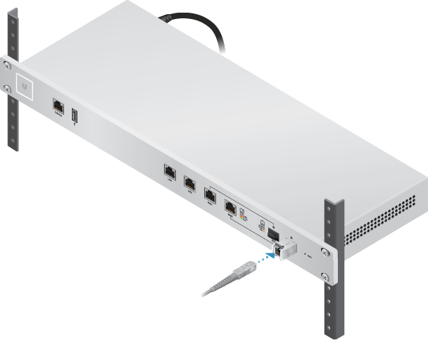
For information about compatible fiber SFP modules, visit: community.ubnt.com/unifi
Specifications
|
USG-PRO-4 |
|
|
Dimensions |
484 x 44 x 164 mm (19.06 x 1.73 x 6.46") |
|---|---|
|
Weight |
2.30 kg (5.07 lb) |
|
Networking Interfaces |
|
| Serial Console Port | (1) RJ45 Serial Port |
| Data Ports | (2) 10/100/1000 RJ45 Ports (2) 10/100/1000 RJ45/SFP Combination Ports |
|
Max. Power Consumption |
40W |
|
Power Supply |
Internal AC/DC Power Adapter, 60W (24V, 2.5A) |
|
Supported Voltage Range |
110 - 240VAC |
|
LEDs |
|
| System | Status |
| Data Ports | Speed/Link/Activity |
|
Layer 3 Forwarding Performance |
|
| Packet Size: 64 Bytes | 2,400,000 pps |
| Packet Size: 512 Bytes or Larger | 4 Gbps (Line Rate) |
|
Processor |
Dual-Core 1 GHz, MIPS64 with Hardware Acceleration for Packet Processing |
|
System Memory |
2 GB DDR3 RAM |
|
On-Board Flash Storage |
4 GB |
|
Rackmount |
Yes |
|
Operating Temperature |
-10 to 45° C (14 to 113° F) |
|
Operating Humidity |
10 to 90% Noncondensing |
|
Certifications |
CE, FCC, IC |
Safety Notices
- Read, follow, and keep these instructions.
- Heed all warnings.
- Only use attachments/accessories specified by the manufacturer.
| WARNING: Failure to provide proper ventilation may cause fire hazard. Keep at least 20 mm of clearance next to the ventilation holes for adequate airflow. |
|---|

| WARNING: To reduce the risk of fire or electric shock, do not expose this product to rain or moisture. |
|---|
| WARNING: Do not use this product in location that can be submerged by water. |
|---|
| WARNING: Avoid using this product during an electrical storm. There may be a remote risk of electric shock from lightning. |
|---|
Electrical Safety Information
- Compliance is required with respect to voltage, frequency, and current requirements indicated on the manufacturer’s label. Connection to a different power source than those specified may result in improper operation, damage to the equipment or pose a fire hazard if the limitations are not followed.
- There are no operator serviceable parts inside this equipment. Service should be provided only by a qualified service technician.
- This equipment is provided with a detachable power cord which has an integral safety ground wire intended for connection to a grounded safety outlet.
- Do not substitute the power cord with one that is not the provided approved type. Never use an adapter plug to connect to a 2-wire outlet as this will defeat the continuity of the grounding wire.
- The equipment requires the use of the ground wire as a part of the safety certification, modification or misuse can provide a shock hazard that can result in serious injury or death.
- Contact a qualified electrician or the manufacturer if there are questions about the installation prior to connecting the equipment.
- Protective earthing is provided by Listed AC adapter. Building installation shall provide appropriate short-circuit backup protection.
- Protective bonding must be installed in accordance with local national wiring rules and regulations.
Limited Warranty
The limited warranty requires the use of arbitration to resolve disputes on an individual basis, and, where applicable, specify arbitration instead of jury trials or class actions.
Compliance
FCC
Changes or modifications not expressly approved by the party responsible for compliance could void the user’s authority to operate the equipment.
This device complies with Part 15 of the FCC Rules. Operation is subject to the following two conditions.
- This device may not cause harmful interference, and
- This device must accept any interference received, including interference that may cause undesired operation.
This equipment has been tested and found to comply with the limits for a Class A digital device, pursuant to Part 15 of the FCC Rules. These limits are designed to provide reasonable protection against harmful interference when the equipment is operated in a commercial environment. This equipment generates, uses, and can radiate radio frequency energy and, if not installed and used in accordance with the instruction manual, may cause harmful interference to radio communications. Operations of this equipment in a residential area is likely to cause harmful interference in which case the user will be required to correct the interference at his own expense.
ISED Canada
CAN ICES-3(A)/NMB-3(A)
Australia and New Zealand
| Warning: This equipment is compliant with Class A of CISPR 32. In a residential environment this equipment may cause radio interference. |
|---|

CE Marking
CE marking on this product represents the product is in compliance with all directives that are applicable to it.
![]()