Package Contents
 |
|---|
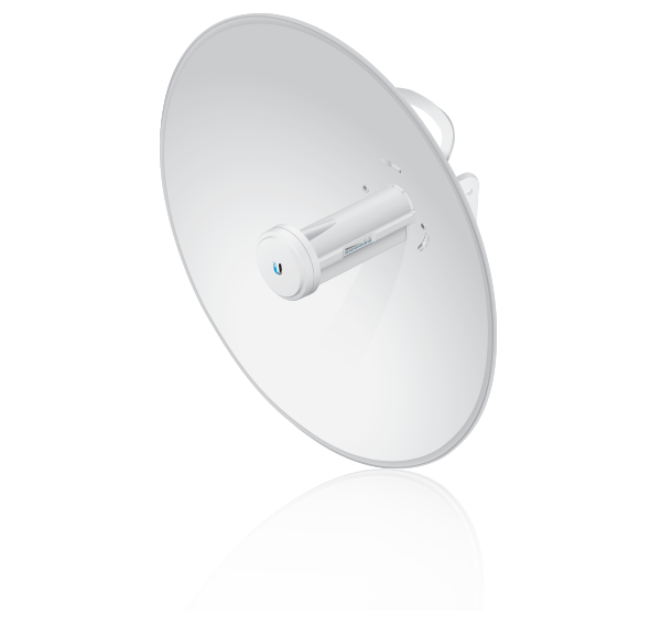
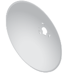
| Dish Reflector |
 |
|---|
| Antenna Feed |
 |
|---|
| Rear Housing |
 |
|---|
| Mounting Bracket |
 |
|---|
| Hex Bolts with Washers (Qty. 4) |
 |
|---|
| Pole Clamp |
 |
|---|
| Carriage Bolts (Qty. 2) |
 |
|---|
| Flange Nuts (Qty. 2) |
 |
|---|
| Gigabit PoE (24V, 0.5A) with Mounting Bracket |
 |
|---|
| Power Cord |
Installation Requirements
- 13 mm wrench
- Shielded Category 5 (or above) cabling with drain wire should be used for all wired Ethernet connections and should be grounded through the AC ground of the PoE.
We recommend that you protect your networks from harmful outdoor environments and destructive ESD events with industrial-grade, shielded Ethernet cable from Ubiquiti. For more details, visit ui.com/toughcable
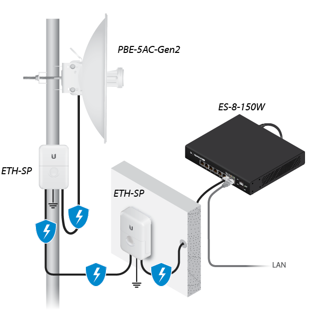
- Surge protection should be used for all outdoor installations. We recommend that you use two Ethernet Surge Protectors, model ETH-SP, one near the PowerBeam and the other at the entry point to the building. The ETH-SP will absorb power surges and safely discharge them into the ground.
Hardware Overview
Bottom View
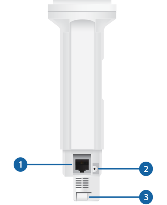
 Ethernet |
|---|
This Gigabit Ethernet port is used to connect the power and should be connected to the LAN and DHCP server. |

Reset Button |
To reset to factory defaults, press and hold the Reset button for more than 10 seconds while the device is powered on. Alternatively, the device may be reset remotely via a Reset button located on the bottom of the Gigabit PoE Adapter. |

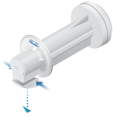
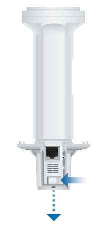
Release Button |
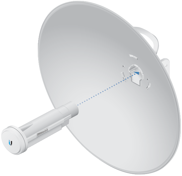
After you assemble the PowerBeam, check the Release button; it should be fully engaged in the Release Button Slot of the Rear Housing. This ensures that the Antenna Feed is locked into place. If you need to remove the Antenna Feed, you must depress the Release button first. |
LEDs
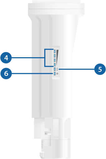

Signal |
|---|
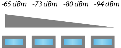
In airOS®, you can modify the threshold value for the wireless signal strength LEDs on the Wireless tab under Signal LED Thresholds. Each LED will light when the wireless signal strength is equal to or greater than the LED’s threshold value. The default threshold values for these LEDs are shown below:
|

Ethernet |
The Ethernet LED will light steady blue when an active Ethernet connection is made and flash when there is activity. |

Power |
The Power LED will light blue when the device is connected to a power source. |
Application Examples
The PowerBeam mounted outdoors with the Dish Reflector installed provides directional outdoor coverage (gain is reflector-dependent).

The PowerBeam mounted outdoors without the Dish Reflector installed provides outdoor-to-indoor coverage using the 3 dBi Antenna Feed only.

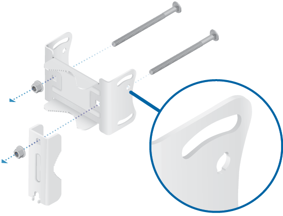
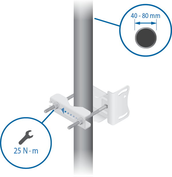
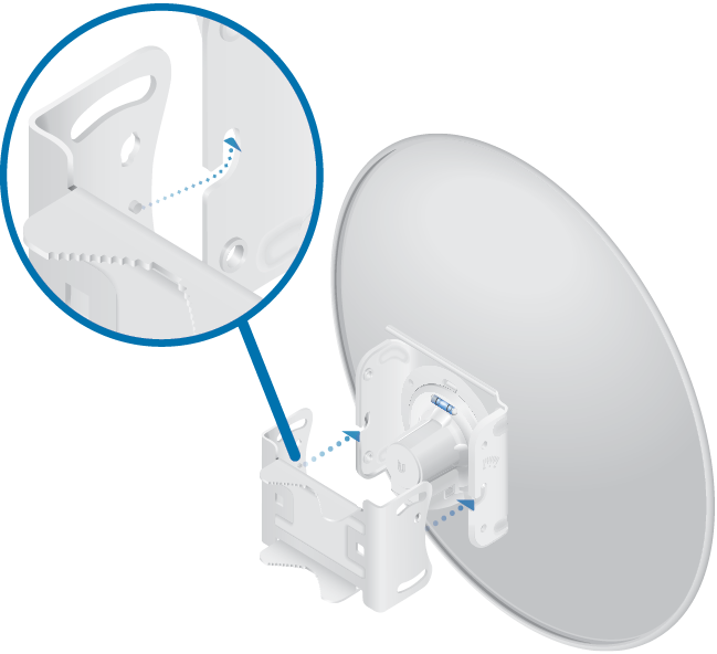
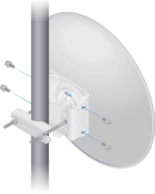
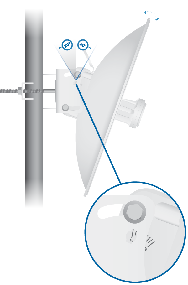
Installation
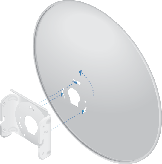
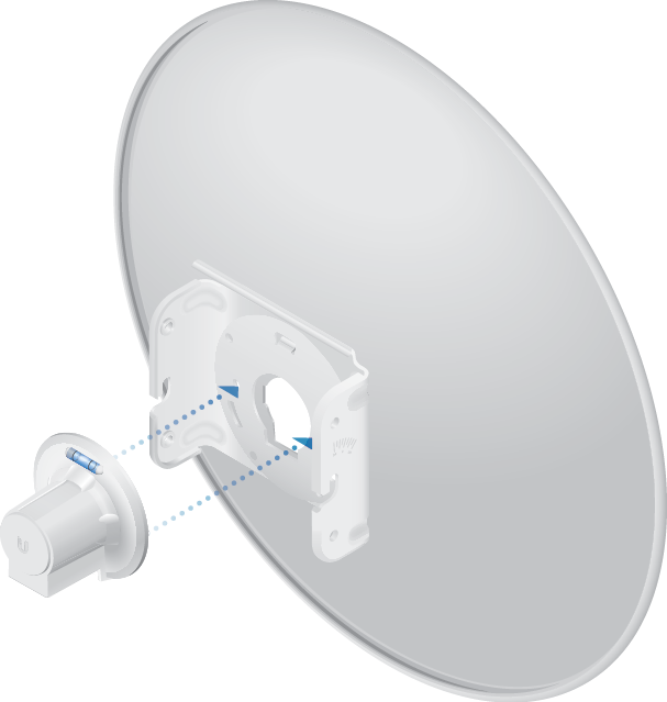

Note: In high-wind environments, you can add support with additional hardware (not included):
- Using the four holes in the Adjustment Bracket as a template, drill four holes into the Dish Reflector with a 4.4 mm or 11/64" drill bit.
- Secure the Dish Reflector to the Adjustment Bracket using M4 screws, washers, and nuts (not included).
- Connect the power using:
- included Gigabit PoE Adapter
- PoE switch

WARNING: The switch port must comply with the power specifications listed in this Quick Start Guide.
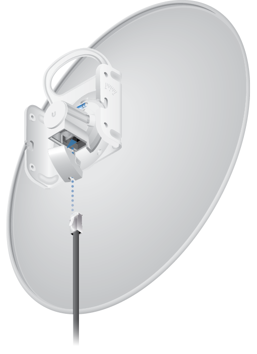
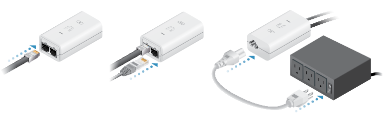
Connecting to the PoE Adapter
- Connect the Ethernet cable from the device to the POE port of the PoE adapter.
- Connect an Ethernet cable from your LAN to the LAN port of the PoE adapter.
- Connect the Power Cord to the adapter, and then plug the Power Cord into a power outlet.
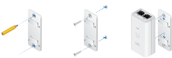
Mounting the PoE Adapter (Optional)
- Remove the PoE Mounting Bracket from the adapter, place the bracket at the desired location, and mark the two holes.
- Pre-drill the holes if necessary, and secure the bracket using two fasteners (not included).
- Align the adapter’s slots with the tabs of the PoE Mounting Bracket, and then slide the adapter down.
Accessing airOS via Wi-Fi
Verify connectivity in the airOS® Configuration Interface using the UISP™ app or Web Portal. Both are available for 15 minutes immediately after you power on the device. If necessary, you can power cycle the device to re-enable its Wi-Fi.
UISP App
- Download the UISP app.

- Connect your device’s Wi-Fi to the SSID named: <model>:<MAC Address>

Note: Ensure that DHCP is enabled on your Wi-Fi adapter.
- Launch the app and follow the on-screen instructions.
Web Portal
- Connect your device’s Wi-Fi to the SSID named: <model>:<MAC Address>
Note: Ensure that your Wi-Fi connection has DHCP enabled.
- Launch your web browser and go to: http://setup.ui.com

- Select your Country and Language. You must agree to the Terms of Use to use the product. Click Continue.
- Create a username and password. Confirm your new password and then click Save.
The airOS Configuration Interface will appear, allowing you to customize your settings as needed. For additional details, refer to the User Guide available at ui.com/download/airmax-ac
Installer Compliance Responsibility
Devices must be professionally installed and it is the professional installer’s responsibility to make sure the device is operated within local country regulatory requirements.
Antenna
Select your antenna from the list. If Calculate EIRP Limit is enabled, transmit output power is automatically adjusted to comply with the regulations of the applicable country. For a Custom antenna, Antenna Gain is entered manually. Note the requirements and antenna types listed below.
Cable Loss (When applicable)
Enter the cable loss in dB. Output power is adjusted to compensate for loss between the radio and the antenna.
Certified Antenna Types
This radio transmitter FCC ID: SWX-PBE5ACG2 / IC: 6545A-PBE5ACG2 has been approved by FCC / ISED Canada to operate with the antenna types listed below with the maximum permissible gain for each antenna type indicated. Antenna types not included in this list or having a gain greater than the maximum gain indicated for that type, are strictly prohibited for use with this device.
|
Antenna |
Frequency |
Gain |
|---|---|---|
|
Dish |
5 GHz |
25 dBi |
Specifications
|
PBE-5AC-Gen2 |
|
|
Dimensions |
420 x 420 x 230 mm (16.54 x 16.54 x 9.06") |
|---|---|
|
Weight |
2.22 kg (4.89 lb) |
|
Gain |
25 dBi |
|
Networking Interface |
(1) 10/100/1000 Ethernet Port |
|
Processor |
MIPS 74Kc |
|
Enclosure Characteristics |
|
| Antenna Feed | Outdoor UV Stabilized Plastic |
| Dish Reflector | Powder-Coated SPCC |
|
Max. Power Consumption |
8.5W |
|
Max. TX Power |
24 dBm |
|
Power Supply |
24V, 0.5A Gigabit PoE Adapter (Included) |
|
Power Method |
Passive PoE (Pairs 4, 5+; 7, 8 Return) |
|
Supported Voltage Range |
20 to 26VDC |
|
Wind Loading |
380 N @ 200 km/h (85.4 lbf @ 125 mph) |
|
Wind Survivability |
200 km/h (125 mph) |
|
Mounting |
Pole Mounting Kit Included |
|
Operating Temperature |
-40 to 70° C (-40 to 158° F) |
|
Operating Humidity |
5 to 95% Noncondensing |
|
Shock and Vibrations |
ETSI300-019-1.4 |
|
Certifications |
CE, FCC, IC |
|
Operating Frequency (MHz) |
||
|
Worldwide |
5150 - 5875 |
|
|---|---|---|
|
US/CA |
U-NII-1 |
5150 - 5250 |
|
U-NII-2A |
5250 - 5350 | |
|
U-NII-2C |
5470 - 5725 | |
|
U-NII-3 |
5725 - 5850 |
|
|
Management Radio (MHz) |
|
|
Worldwide |
2412 - 2472 |
|---|---|
|
US/CA |
2412 - 2462 |
Safety Notices
- Read, follow, and keep these instructions.
- Heed all warnings.
- Only use attachments/accessories specified by the manufacturer.
| WARNING: Do not use this product in location that can be submerged by water. |
|---|

| WARNING: Avoid using this product during an electrical storm. There may be a remote risk of electric shock from lightning. |
|---|
Electrical Safety Information
- Compliance is required with respect to voltage, frequency, and current requirements indicated on the manufacturer’s label. Connection to a different power source than those specified may result in improper operation, damage to the equipment or pose a fire hazard if the limitations are not followed.
- There are no operator serviceable parts inside this equipment. Service should be provided only by a qualified service technician.
- This equipment is provided with a detachable power cord which has an integral safety ground wire intended for connection to a grounded safety outlet.
- Do not substitute the power cord with one that is not the provided approved type. Never use an adapter plug to connect to a 2-wire outlet as this will defeat the continuity of the grounding wire.
- The equipment requires the use of the ground wire as a part of the safety certification, modification or misuse can provide a shock hazard that can result in serious injury or death.
- Contact a qualified electrician or the manufacturer if there are questions about the installation prior to connecting the equipment.
- Protective earthing is provided by Listed AC adapter. Building installation shall provide appropriate short-circuit backup protection.
- Protective bonding must be installed in accordance with local national wiring rules and regulations.
Limited Warranty
The limited warranty requires the use of arbitration to resolve disputes on an individual basis, and, where applicable, specify arbitration instead of jury trials or class actions.
Compliance
FCC
Changes or modifications not expressly approved by the party responsible for compliance could void the user’s authority to operate the equipment.
This device complies with Part 15 of the FCC Rules. Operation is subject to the following two conditions.
- This device may not cause harmful interference, and
- This device must accept any interference received, including interference that may cause undesired operation.
This equipment has been tested and found to comply with the limits for a Class A digital device, pursuant to part 15 of the FCC Rules. These limits are designed to provide reasonable protection against harmful interference when the equipment is operated in a commercial environment. This equipment generates, uses, and can radiate radio frequency energy and, if not installed and used in accordance with the instruction manual, may cause harmful interference to radio communications. Operations of this equipment in a residential area is likely to cause harmful interference in which case the user will be required to correct the interference at his own expense.
This radio transmitter has been approved by FCC.
ISED Canada
CAN ICES-3(A)/NMB-3(A)
This device complies with ISED Canada licence-exempt RSS standard(s). Operation is subject to the following two conditions:
- This device may not cause interference, and
- This device must accept any interference, including interference that may cause undesired operation of the device.
This radio transmitter has been approved by ISED Canada.
The device for operation in the band 5150-5250 MHz is only for indoor use to reduce the potential for harmful interference to co-channel mobile satellite systems.
CAN ICES-3(A)/NMB-3(A)
Le présent appareil est conforme aux CNR d’ISDE Canada applicables aux appareils radio exempts de licence. L’exploitation est autorisée aux deux conditions suivantes :
- l’appareil ne doit pas produire de brouillage;
- l’appareil doit accepter tout brouillage radioélectrique subi, même si le brouillage est susceptible d’en compromettre le fonctionnement.
Le présent émetteur radio a été approuvé par ISDE Canada.
Les dispositifs fonctionnant dans la bande 5150-5250 MHz sont réservés uniquement pour une utilisation à l’intérieur afin de réduire les risques de brouillage préjudiciable aux systèmes de satellites mobiles utilisant les mêmes canaux.
IMPORTANT NOTE
Radiation Exposure Statement
- This equipment complies with radiation exposure limits set forth for an uncontrolled environment.
- This equipment should be installed and operated with minimum distance 137 cm between the radiator and your body.
- This transmitter must not be co-located or operating in conjunction with any other antenna or transmitter.
AVIS IMPORTANT
Déclaration sur l’exposition aux rayonnements
- Cet équipement est conforme aux limites prévues pour l’exposition aux rayonnements dans un environnement non contrôlé.
- Lors de l’installation et de la mise en fonctionnement de l’équipement, assurez-vous qu’il y ait une distance minimale de 137 cm entre l’élément rayonnant et vous.
- Cet émetteur ne doit être installé à proximité d’aucune autre antenne ni d’aucun autre émetteur, et ne doit être utilisé conjointement à aucun autre de ces appareils.
Australia and New Zealand
| Warning: This equipment is compliant with Class A of CISPR 32. In a residential environment this equipment may cause radio interference. |
|---|

Brazil
| Nota: Este equipamento não tem direito à proteção contra interferência prejudicial e não pode causar interferência em sistemas devidamente autorizados. |
|---|
CE Marking
CE marking on this product represents the product is in compliance with all directives that are applicable to it.
![]()
Country List | ||||||||||||||||||||||||||||||||
| ||||||||||||||||||||||||||||||||
BFWA (Broadband Fixed Wireless Access) members noted in blue |
| Note: This device meets Max. TX power limit per ETSI regulations. |
|---|
The following apply to products that operate in the 5 GHz frequency range:
| Note: This device is restricted to indoor use only when operating in the 5150 - 5350 MHz frequency range within all member states. |
|---|
| Note: Operation in the 5.8 GHz frequency band is prohibited in BFWA member states. Other countries listed may use the 5.8 GHz frequency band. |
|---|