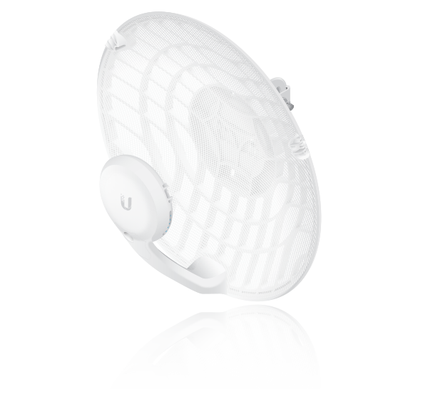
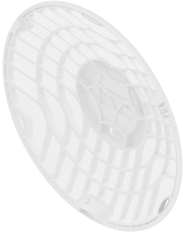
Package Contents
 |
|---|
| Dish |
 |
|---|
| Main Arm |
 |
|---|
| Stabilizer Arms (Qty. 2) |
 |
|---|
| Mounting Bracket |
 |
|---|
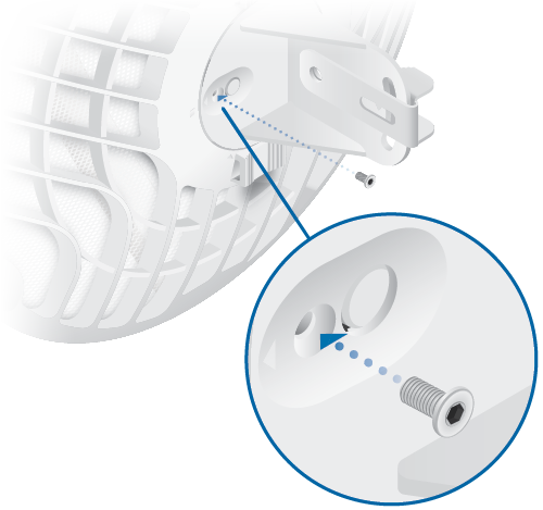
| Screw |
 |
|---|
| U-Clamp |
 |
|---|
| Flat Washers (Qty. 2) |
 |
|---|
| Lock Washers (Qty. 2) |
 |
|---|
| Flange Nuts (Qty. 2) |
 |
|---|
| Gigabit PoE (24V, 0.5A) with Mounting Bracket |
 |
|---|
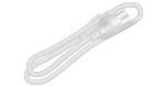
| Power Cord |
Installation Requirements
- Clear line of sight between GigaBeam AP and station
- Vertical mounting orientation
- Mounting point:
- At least 1 m below the highest point on the structure
- For tower installations, at least 3 m below the top of the tower
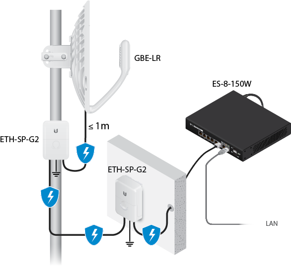
- Outdoor, shielded Category 6 (or above) cabling and shielded RJ45 connectors are required for all wired Ethernet connections.
- Surge protection should be used for all outdoor installations. We recommend that you use two Ethernet Surge Protectors, model ETH-SP-G2, one near the device and the other at the entry point to the building. The ETH-SP-G2 will absorb power surges and safely discharge them into the ground.
| Note: For guidelines about grounding and lightning protection, follow your local electrical regulatory codes. |
|---|
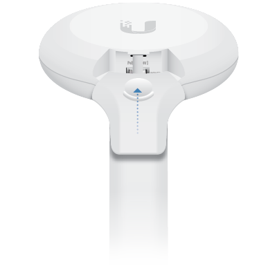
Hardware Overview
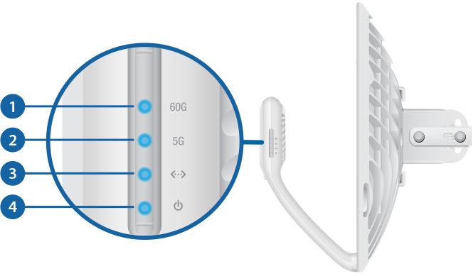

60 GHz LED |
|
|---|---|
Lights steady blue when the 60 GHz link is ready. |
|

5 GHz LED |
|
Lights steady blue when the 5 GHz link is ready. |
|
 LAN LED |
|
The LED will light steady blue when an active Ethernet connection is made to the Ethernet port and flash when there is activity. |
|
 Power/Status LED |
|
Flashing White |
Bootup in progress. |
White |
Ready for use, not connected to Ubiquiti Internet Service Provider (UISP™). See “UISP Management”. |
Blue |
Ready for use, connected to UISP. |
Steady Blue with Occasional Flashing |
Ready for use, unable to connect to UISP, check connection to UISP server. |
Quickly Flashing Blue |
Used to locate a device in UISP. |
Alternating |
Firmware upgrade in progress. |
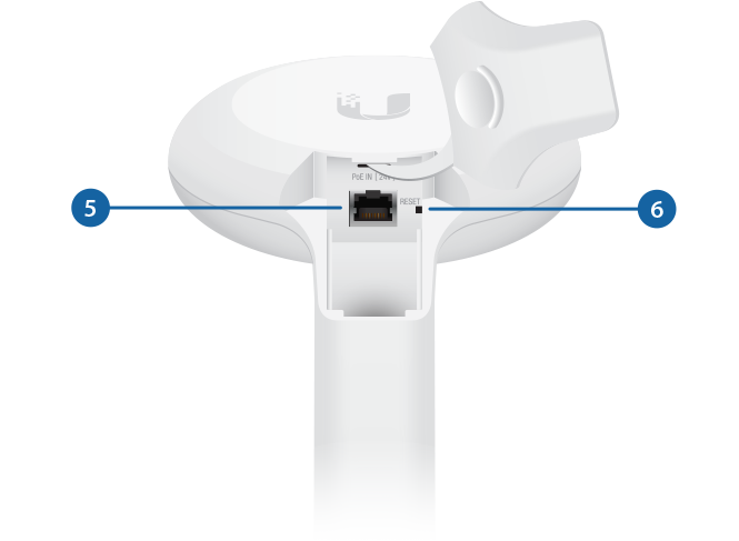
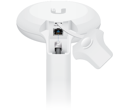
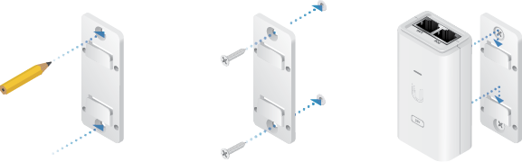
 PoE IN Port |
|
This Gigabit Ethernet port is used to connect the power and should be connected to the LAN and DHCP server. Default IP address: 192.168.1.20. |
|
 Reset Button |
|
To reset to factory defaults, press and hold the Reset button for more than 10 seconds while the device is powered on. Alternatively, the device may be reset remotely via a Reset button located on the bottom of the Gigabit PoE Adapter. |
|
Installation
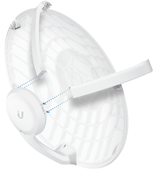
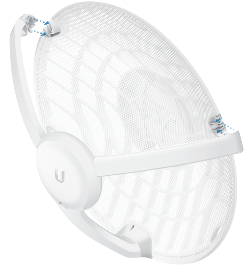
OPTIONAL
Attach the stabilizer arms for added support.
(This is recommended for long-range installations.)
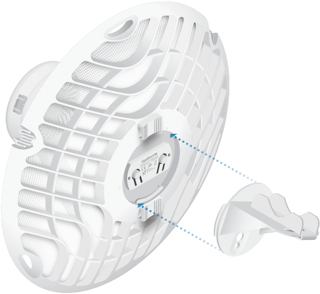
| Note: The GBE-LR can mount on either side of the pole. This section shows the GBE-LR mounted on the left; the procedure for mounting on the right is similar. |
|---|
Left | OR |
Right |
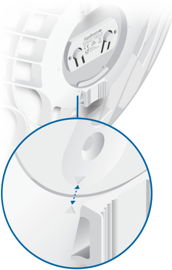
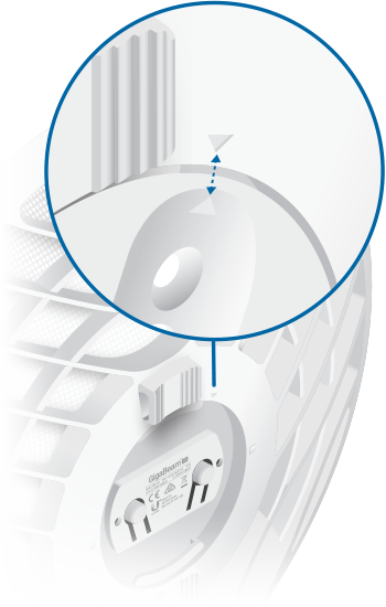
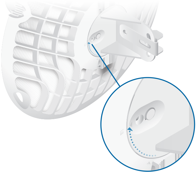
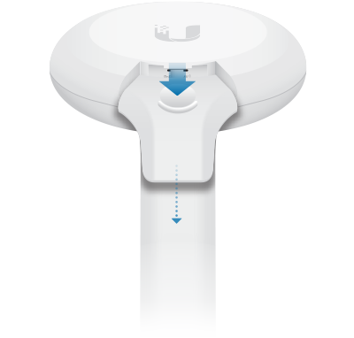
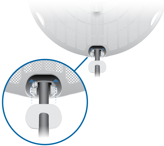
| Note: Rotate the Mounting Bracket clockwise until it locks into position. |
|---|
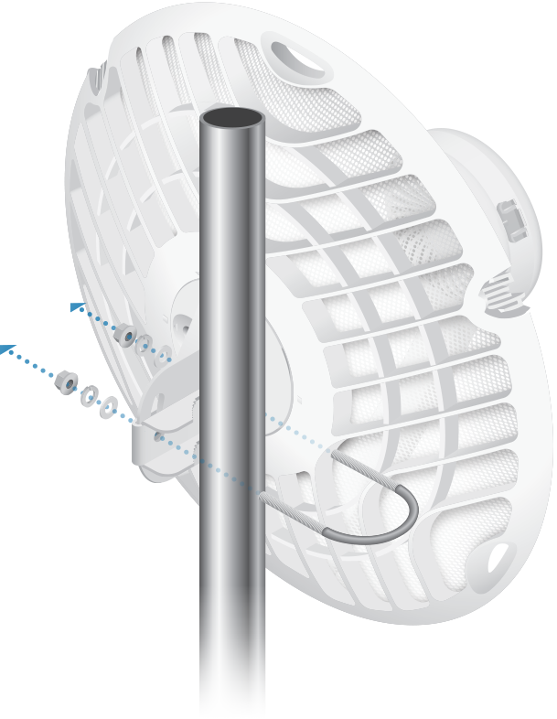
(Pole not shown)
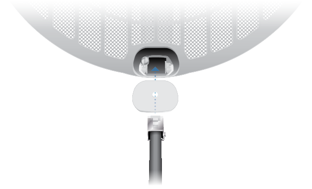
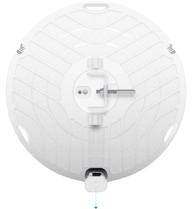
Connecting Power
|
|
WARNING: The switch port must comply with the power specifications listed in “Specifications”. |
|---|

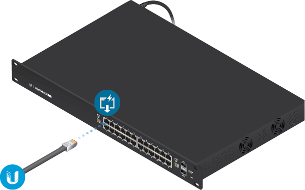
OR
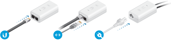
Optional
Configuration
The device is set to DHCP by default, so it will try to automatically obtain an IP address. If that fails, it will use the default fallback IP address, 192.168.1.20. Proceed to the appropriate section, DHCP or “Fallback IP Address”:
DHCP
Use one of the following methods:
- Set up the DHCP server to provide a specific IP address to the device based on its MAC address (on the label).
- Let the device obtain an IP address and then check the DHCP server to see which IP address was assigned.
- Connect a computer to your network and configure the Ethernet adapter on your computer with a static IP address on the 192.168.1.x subnet.
- Launch your web browser. In the address field, type: https://192.168.1.20
Then press enter (PC) or return (Mac).

- Select your Country and Language. You must agree to the Terms of Use to use the product. Click Continue.
- Enter a Username and Password, confirm the Password, and click Save.
- Click the
 icon.
icon. - Configure the following settings:
- For one device, enable Access Point mode. For the other device (the Station), keep Access Point disabled.
- Enter a name in the SSID field. This must be the same on both the AP and the Station.
- In the WPA2 Preshared Key field, enter a combination of alphanumeric characters (0-9, A-Z, or a-z).

Note: The key is an alphanumeric password between 8 and 63 characters long.
- Click Save Changes.
- Configure each device (AP and Station) with a unique IP address:
- Click the
 icon.
icon. - Review the Network settings to ensure that each device has a unique IP address. Each can get its IP address via DHCP, or use a static IP address.
- DHCP By default DHCP client is enabled; if there is a DHCP server on your network, the device will receive its address via DHCP.
- Static Select this option to disable the DHCP client and enter a static IP address.
Note: If DHCP client fails, the device will use the fallback IP address: 192.168.1.20
- Click Save Changes.
- Click the
Fallback IP Address
- Ensure that your computer (or other host machine) is connected to the same LAN as the GigaBeam.
- Configure the Ethernet adapter on your host system with a static IP address on the 192.168.1.x subnet.
- Launch your web browser. Type https://192.168.1.20 in the address field, and press enter (PC) or return (Mac).
- Select your Country and Language. You must agree to the Terms of Use to use the product. Click Continue.
- Enter a Username and Password, confirm the Password, and click Save.
- Click the icon.
- Configure the following settings:
- For one device, enable Access Point mode. For the other device (the Station), keep Access Point disabled.
- Enter a name in the SSID field. This must be the same on both the AP and the Station.
- In the WPA2 Preshared Key field, enter a combination of alphanumeric characters (0-9, A-Z, or a-z).
Note: The key is an alphanumeric password between 8 and 63 characters long.
- Click Save Changes.
- Configure each device (AP and Station) with a unique IP address:
- Click the icon.
- Review the Network settings to ensure that each device has a unique IP address. Each can get its IP address via DHCP, or use a static IP address.
- DHCP By default DHCP client is enabled; if there is a DHCP server on your network, the device will receive its address via DHCP.
- Static Select this option to disable the DHCP client and enter a static IP address.
Note: If DHCP client fails, the device will use the fallback IP address: 192.168.1.20
- Click Save Changes.
- Click the
Repeat the instructions in the “Configuration” section on the other GigaBeam.
UISP Management
You can manage your device using UISP, which lets you configure, monitor, upgrade, and back up your devices using a single application. Get started at uisp.ui.com
Alignment
Tips
- To accurately align the radios for best performance, you MUST align only one end of the link at a time.
- You may need to use additional hardware to compensate for issues such as the improper orientation of a mounting pole or significant elevation differences between radios.
Establishing a Link
Adjust the aim of the AP and the Station to establish a link.
|
|
Note: The AP must be aimed first at the Station because the Station does not transmit any RF signal until it detects transmissions from the AP. |
|---|
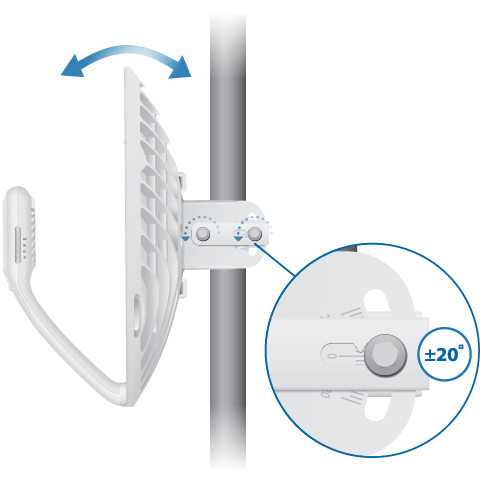
- AP Visually aim the AP at the Station by loosening the Flange Nuts on the Mounting Bracket to allow adjustments to the azimuth and the elevation.
- Station Visually aim the Station at the AP. To adjust the Station’s position, adjust the azimuth and elevation as described in step 1.
- Open the Configuration Interface. Select Tools and then select Align Antenna.
- Repeat steps 1-2 until you have achieved an optimal link and both the 60G and 5G LEDs are solidly lit blue. This ensures the best possible data rate between the radios.
- Lock the alignment on both radios by tightening all the nuts.
- Observe the signal level of each radio to ensure that the values remain constant while tightening the nuts. If any value changes during the locking process, loosen the nuts, finalize the alignment of each radio again, and retighten the nuts.
Adjust the azimuth:
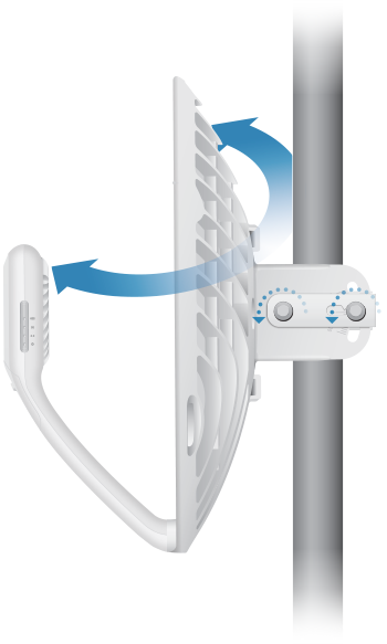
Adjust the elevation:
| Note: Do NOT make simultaneous adjustments on the AP and Station. |
|---|
| Note: Maximum signal strength can best be achieved by iteratively sweeping through both azimuth and elevation. |
|---|
Installer Compliance Responsibility
Devices must be professionally installed and it is the professional installer’s responsibility to make sure the device is operated within local country regulatory requirements.
Antenna
The 5GHz Output Power field is provided to the professional installer to assist in meeting regulatory requirements.
Specifications
|
GBE-LR |
|
|
Dimensions |
415 x 415 x 303 mm (16.34 x 16.34 x 11.93") |
|---|---|
|
Weight |
|
| Without Mount | 1.4 kg (3.09 lb) |
| With Mount | 1.8 kg (3.97 lb) |
|
Enclosure |
Aluminum, UV-stabilized Polycarbonate |
|
Antenna Gain |
|
| 5 GHz | 11 dBi |
| 60 GHz | 38 dBi |
|
Networking Interface |
(1) 10/100/1000 Mbps Ethernet Port |
|
Max. Power Consumption |
11W |
|
Power Method |
Passive PoE, Pins 4, 5+ and 7, 8- |
|
Power Supply |
24VDC, 0.5A Gigabit PoE Adapter (Included) |
|
Voltage Range |
+22 to +26VDC |
|
LEDs |
Power/Ethernet/5G/60G |
|
Wind Loading |
56 N @ 200 km/h (12.6 lbf @ 125 mph) |
|
Wind Survivability |
200 km/h (125 mph) |
|
Mounting |
Pole Mount (Included) |
|
ESD/EMP Protection |
± 24kV Contact/Air |
|
Operating Temperature |
-40 to 60° C (-40 to 140° F) |
|
Operating Humidity |
5 to 95% Noncondensing |
|
Certifications |
FCC, IC, CE |
|
Radio |
|
|
Max. Conducted TX Power |
|
|---|---|
| 5/60 GHz Combined | 25 dBm |
|
Channel Bandwidth |
|
| 60 GHz | 2160 MHz |
| 5 GHz | 20/40/80 MHz |
|
Operating Frequency (MHz) |
||
|
US/CA |
U-NII-1 |
5150 - 5250 |
|---|---|---|
U-NII-2A | 5250 - 5350 | |
U-NII-2C | 5470 - 5725 | |
U-NII-3 | 5725 - 5850 | |
|
57,000 - 66,000 |
||
|
Worldwide |
5180 - 5875 |
|
|
Management Radio (MHz) |
|
|
Worldwide |
2412 - 2472 |
|---|---|
|
US/CA |
2412 - 2462 |
Safety Notices
- Read, follow, and keep these instructions.
- Heed all warnings.
- Only use attachments/accessories specified by the manufacturer.
| WARNING: Do not use this product in location that can be submerged by water. |
|---|

| WARNING: Avoid using this product during an electrical storm. There may be a remote risk of electric shock from lightning. |
|---|
Electrical Safety Information
- Compliance is required with respect to voltage, frequency, and current requirements indicated on the manufacturer’s label. Connection to a different power source than those specified may result in improper operation, damage to the equipment or pose a fire hazard if the limitations are not followed.
- There are no operator serviceable parts inside this equipment. Service should be provided only by a qualified service technician.
- This equipment is provided with a detachable power cord which has an integral safety ground wire intended for connection to a grounded safety outlet.
- Do not substitute the power cord with one that is not the provided approved type. Never use an adapter plug to connect to a 2-wire outlet as this will defeat the continuity of the grounding wire.
- The equipment requires the use of the ground wire as a part of the safety certification, modification or misuse can provide a shock hazard that can result in serious injury or death.
- Contact a qualified electrician or the manufacturer if there are questions about the installation prior to connecting the equipment.
- Protective earthing is provided by Listed AC adapter. Building installation shall provide appropriate short-circuit backup protection.
- Protective bonding must be installed in accordance with local national wiring rules and regulations.
Limited Warranty
The limited warranty requires the use of arbitration to resolve disputes on an individual basis, and, where applicable, specify arbitration instead of jury trials or class actions.
Compliance
FCC / CAN ICES-3(A)/NMB-3(A)
Changes or modifications not expressly approved by the party responsible for compliance could void the user’s authority to operate the equipment.
This device complies with Part 15 of the FCC Rules and ISED Canada licence-exempt RSS standard(s). Operation is subject to the following two conditions.
- This device may not cause harmful interference, and
- This device must accept any interference received, including interference that may cause undesired operation.
Le présent appareil est conforme aux CNR d’ISDE Canada applicables aux appareils radio exempts de licence. L’exploitation est autorisée aux deux conditions suivantes :
- l’appareil ne doit pas produire de brouillage;
- l’appareil doit accepter tout brouillage radioélectrique subi, même si le brouillage est susceptible d’en compromettre le fonctionnement.
This equipment has been tested and found to comply with the limits for a Class A digital device, pursuant to part 15 of the FCC Rules. These limits are designed to provide reasonable protection against harmful interference when the equipment is operated in a commercial environment. This equipment generates, uses, and can radiate radio frequency energy and, if not installed and used in accordance with the instruction manual, may cause harmful interference to radio communications. Operations of this equipment in a residential area is likely to cause harmful interference in which case the user will be required to correct the interference at his own expense.
This radio transmitter FCC ID: SWX-GBELR / IC: 6545A-GBELR has been approved by FCC / ISED Canada.
The device for operation in the band 5150-5250 MHz is only for indoor use to reduce the potential for harmful interference to co-channel mobile satellite systems.
Les dispositifs fonctionnant dans la bande 5150-5250 MHz sont réservés uniquement pour une utilisation à l’intérieur afin de réduire les risques de brouillage préjudiciable aux systèmes de satellites mobiles utilisant les mêmes canaux.
IMPORTANT NOTE:
Radiation Exposure Statement:
- This equipment complies with radiation exposure limits set forth for an uncontrolled environment.
- This equipment should be installed and operated with minimum distance 110 cm between the radiator and your body.
- This transmitter must not be co-located or operating in conjunction with any other antenna or transmitter.
AVIS IMPORTANT :
Déclaration sur l’exposition aux rayonnements :
- Cet équipement est conforme aux limites prévues pour l’exposition aux rayonnements dans un environnement non contrôlé.
- Lors de l’installation et de la mise en fonctionnement de l’équipement, assurez-vous qu’il y ait une distance minimale de 110 cm entre l’élément rayonnant et vous.
- Cet émetteur ne doit être installé à proximité d’aucune autre antenne ni d’aucun autre émetteur, et ne doit être utilisé conjointement à aucun autre de ces appareils.
Australia and New Zealand
| Warning: This equipment is compliant with Class A of CISPR 32. In a residential environment this equipment may cause radio interference. |
|---|

Brazil
| Nota: Este equipamento não tem direito à proteção contra interferência prejudicial e não pode causar interferência em sistemas devidamente autorizados. |
|---|

CE Marking
CE marking on this product represents the product is in compliance with all directives that are applicable to it.
![]()
Country List | ||||||||||||||||||||||||||||||||
| ||||||||||||||||||||||||||||||||
BFWA (Broadband Fixed Wireless Access) members noted in blue |
| Note: This device meets Max. TX power limit per ETSI regulations. |
|---|
| Note: Fixed service or any restrictions for authorization of use shall follow local country regulations. |
|---|
The following apply to products that operate in the 5 GHz frequency range:
| Note: This device is restricted to indoor use only when operating in the 5150 - 5350 MHz frequency range within all member states. |
|---|
| Note: All countries listed may operate at 30 dBm. BFWA member states may operate at 36 dBm. |
|---|
| Note: Operation in the 5.8 GHz frequency band is prohibited in BFWA member states. Other countries listed may use the 5.8 GHz frequency band. |
|---|