Package Contents
 |
|---|
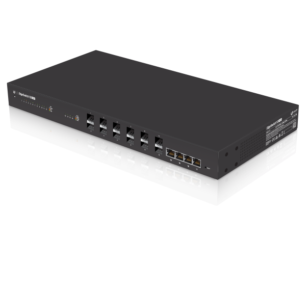
| EdgeSwitch |
 |
|---|
| Rack-Mount Brackets (Qty. 2) |
 |
|---|
| Bracket Screws (M4, Qty. 8) |
 |
|---|
| Mounting Screws (Qty. 4) |
 |
|---|
| Cage Nuts (Qty. 4) |
 |
|---|
| Power Cord |
Installation Requirements
- Phillips screwdriver (for rack- or wall-mounting)
- Standard-sized, 19" wide rack with a minimum of 1U height available (for rack-mounting)
- Use compatible fiber SFP modules with the appropriate fiber optic cabling. For information about compatible fiber SFP modules, visit: ubnt.link/SFP_DAC_Compatibility
- For indoor applications, use Category 5 (or above) UTP cabling approved for indoor use.
- For outdoor applications, shielded Category 5 (or above) cabling should be used for all wired Ethernet connections and should be grounded through the AC ground of the power supply.
We recommend that you protect your networks from harmful outdoor environments and destructive ESD events with industrial-grade, shielded Ethernet cable from Ubiquiti. For more details, visit: ui.com/toughcable
| Note: Although the cabling can be located outdoors, the EdgeSwitch itself should be housed inside a protective enclosure. |
|---|

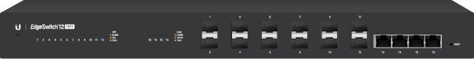
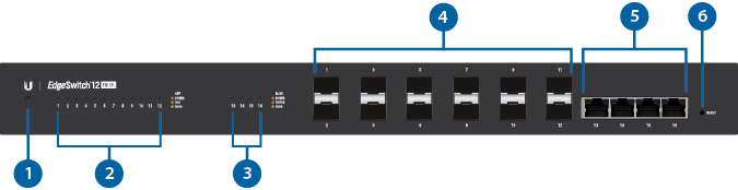
Hardware Overview
|
|
Note: The System LED functionality has been updated with firmware v1.8.0. We recommend that you update the EdgeSwitch to the latest firmware. |
|---|

System LED |
|||
|---|---|---|---|
|
Flashing White |
Bootup in progress. |
||
|
White |
Ready for use, not connected to Ubiquiti® Network Management System (UNMS™). |
||
|
Blue |
Ready for use, connected to UNMS. |
||
|
Steady Blue with Occasional Flashing |
Ready for use, unable to connect to UNMS, check connection to UNMS server. |
||
|
Quickly Flashing Blue |
Used to locate a device in UNMS. |
||
|
Alternating |
Firmware upgrade in progress. |
||

SFP Speed/Link/Act LED (Ports 1 - 12) |
|||
Off |
No Link |
||
Amber |
Link Established at 100 Mbps Flashing Indicates Activity |
||
Green |
Link Established at 1000 Mbps (1 Gbps) Flashing Indicates Activity |
||

RJ45 Speed/Link/Act LED (Ports 13 - 16) |
|||
Off |
No Link |
||
Amber |
Link Established at 10/100 Mbps Flashing Indicates Activity |
||
Green |
Link Established at 1000 Mbps (1 Gbps) Flashing Indicates Activity |
||

SFP (Ports 1 - 12) |
|||
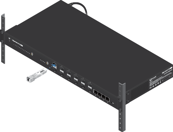
Hot-swappable SFP ports support 1 Gbps connections. Ports 1-8 also support 100 Mbps. |
|||

RJ45 (Ports 13 - 16) |
|||
RJ45 ports support 10/100/1000 Ethernet connections. |
|||

Reset Button |
|||
There are two methods to reset the EdgeSwitch to factory defaults: Runtime Reset (Recommended) The EdgeSwitch should be running after bootup is complete, and the System LED is white. Press and hold the Reset button. The EdgeSwitch will reboot, and the System LED becomes blue after three seconds. Continue to hold the Reset button for about 15 seconds until the System LED flashes blue for two seconds. This indicates that the EdgeSwitch has reset to its factory defaults. Power-on Reset
|
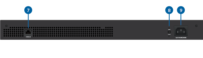
|||

Console |
|||
RJ45 serial console port for Command Line Interface (CLI) management. Use an RJ45-to-DB9, serial console cable, also known as a rollover cable, to connect the Console port to your computer. Then configure the following settings as needed:
|
|||

DC Input |
|||
The 25VDC input can connect a redundant or stand-alone DC power source (not included) with minimum power: 56W, 25 to 16V, and 2.5 mm DC power inline connector.
|
|||

Power |
|||
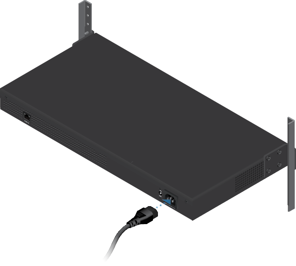
Connect the included Power Cord to the Power port. |
|||
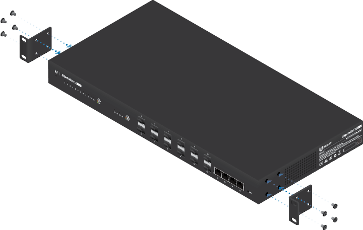
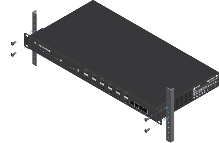
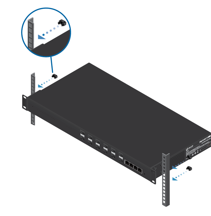
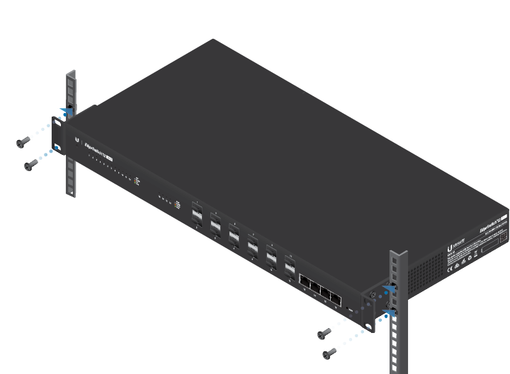
Hardware Installation
Mounting in a Rack (Optional)
OR
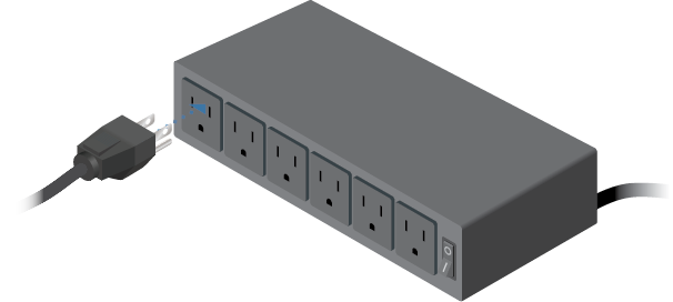
Connecting Power
Connecting SFP
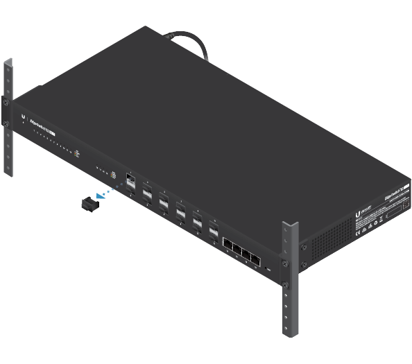
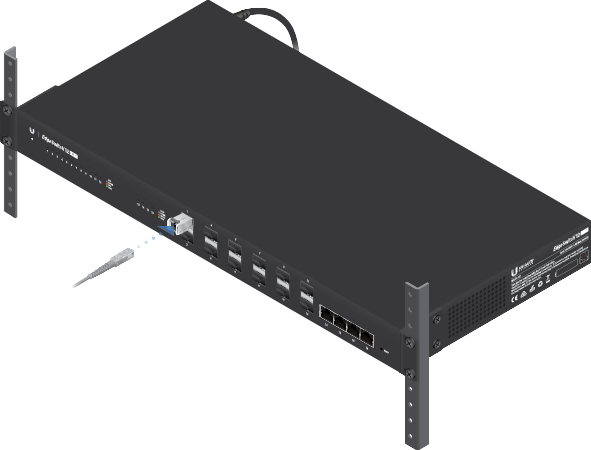
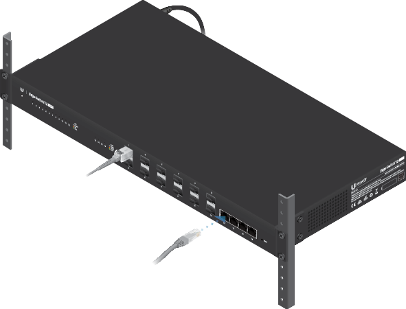
Connecting RJ45
Accessing the Configuration Interface
The EdgeSwitch is set to DHCP by default, so it will try to automatically obtain an IP address. If that fails, then it will use the default fallback IP address, 192.168.1.2. Proceed to the appropriate section, DHCP or “Fallback IP Address”:
DHCP
Use one of the following methods:
- Set up the DHCP server to provide a specific IP address to the EdgeSwitch based on its MAC address (on the label).
- Let the EdgeSwitch obtain an IP address and then check the DHCP server to see which IP address was assigned.
To log in, follow these steps:
- Launch your web browser. Type the appropriate IP address in the address field. Press enter (PC) or return (Mac).
- Enter ubnt in the Username and Password fields. Click Sign In.
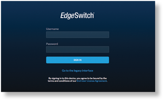
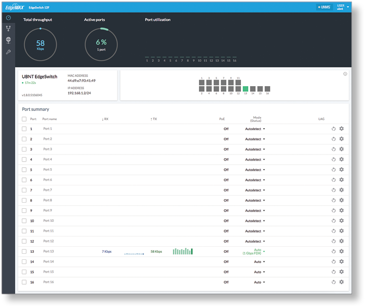
The EdgeSwitch Configuration Interface will appear. Customize additional settings as needed. For more information, refer to the EdgeSwitch documentation, which is available at ui.com/download/edgemax
Fallback IP Address
- Ensure that your computer (or other host system) is connected to the EdgeSwitch.
- Configure the Ethernet adapter on your host system with a static IP address on the 192.168.1.x subnet.
- Launch your web browser. Type the appropriate IP address in the address field (192.168.1.2 is the default fallback IP address). Press enter (PC) or return (Mac).

- Enter ubnt in the Username and Password fields. Click Sign In.
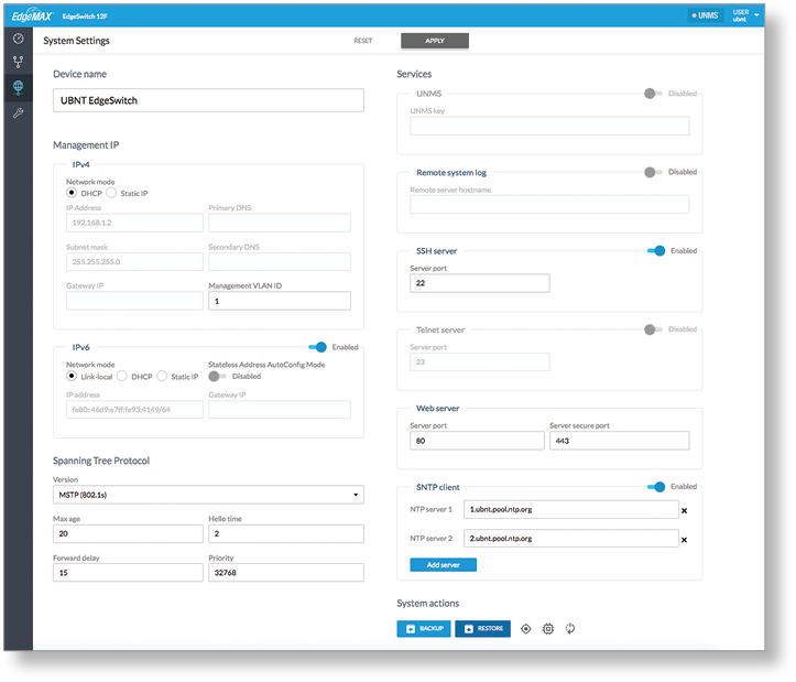
- The EdgeSwitch Configuration Interface will appear. Click the System Settings tab.
- Change the IP Address to a unique IP address. Click Apply.
|
|
Note: If you change the IP settings, then the session will be cut off, and you will need to reconnect to the EdgeSwitch using the new IP address. |
|---|
Customize additional settings as needed. For more information, refer to the EdgeSwitch documentation, which is available at ui.com/download/edgemax
UNMS Management
You can manage your device using UNMS, which lets you configure, monitor, upgrade, and back up your devices using a single application. Get started at www.unms.com
Specifications
|
ES-12F |
|
|
Dimensions |
443 x 221 x 43 mm (17.44 x 8.70 x 1.69") |
|---|---|
|
Weight |
|
| Rack-Mount Brackets Included | 2.68 kg (5.91 lb) |
| Rack-Mount Brackets Excluded | 2.59 kg (5.71 lb) |
|
Total Non-Blocking Line Rate |
16 Gbps |
|
Max. AC Power Consumption |
56W |
|
Power Method |
|
| AC | 100-240VAC/50-60 Hz, Universal Input |
| DC | DC 56W, 25 to 16V, with 2.5 mm DC Power Inline Connector |
|
Power Supply |
AC/DC, Internal, 56W DC |
|
Supported Voltage Range |
100 to 240VAC 25 to 16VDC |
|
LEDs Per Data Port |
Speed/Link/Activity |
|
Interfaces |
|
| Networking Interfaces | (8) 100/1000 Mbps SFP Ethernet Ports (4) 1000 Mbps SFP Ethernet Ports (4) 10/100/1000 Mbps RJ45 Ethernet Ports |
| Management Interface | (1) RJ45 Serial Port Out-of-Band, Ethernet In-Band |
|
Rackmount |
Yes, 1U High |
|
ESD/EMP Protection |
Air: ± 24 kV, Contact: ± 24 kV |
|
Shock and Vibration |
ETSI300-019-1.4 Standard |
|
Operating Temperature |
-5 to 40° C (23 to 104° F) |
|
Operating Humidity |
5 to 95% Noncondensing |
|
Certifications |
CE, FCC, IC |
Safety Notices
- Read, follow, and keep these instructions.
- Heed all warnings.
- Only use attachments/accessories specified by the manufacturer.
| WARNING: Failure to provide proper ventilation may cause fire hazard. Keep at least 20 mm of clearance next to the ventilation holes for adequate airflow. |
|---|

| WARNING: To reduce the risk of fire or electric shock, do not expose this product to rain or moisture. |
|---|
| WARNING: Do not use this product in location that can be submerged by water. |
|---|
| WARNING: Avoid using this product during an electrical storm. There may be a remote risk of electric shock from lightning. |
|---|
Electrical Safety Information
- Compliance is required with respect to voltage, frequency, and current requirements indicated on the manufacturer’s label. Connection to a different power source than those specified may result in improper operation, damage to the equipment or pose a fire hazard if the limitations are not followed.
- There are no operator serviceable parts inside this equipment. Service should be provided only by a qualified service technician.
- This equipment is provided with a detachable power cord which has an integral safety ground wire intended for connection to a grounded safety outlet.
- Do not substitute the power cord with one that is not the provided approved type. Never use an adapter plug to connect to a 2-wire outlet as this will defeat the continuity of the grounding wire.
- The equipment requires the use of the ground wire as a part of the safety certification, modification or misuse can provide a shock hazard that can result in serious injury or death.
- Contact a qualified electrician or the manufacturer if there are questions about the installation prior to connecting the equipment.
- Protective earthing is provided by Listed AC adapter. Building installation shall provide appropriate short-circuit backup protection.
- Protective bonding must be installed in accordance with local national wiring rules and regulations.
Limited Warranty
The limited warranty requires the use of arbitration to resolve disputes on an individual basis, and, where applicable, specify arbitration instead of jury trials or class actions.
Compliance
FCC
Changes or modifications not expressly approved by the party responsible for compliance could void the user’s authority to operate the equipment.
This device complies with Part 15 of the FCC Rules. Operation is subject to the following two conditions.
- This device may not cause harmful interference, and
- This device must accept any interference received, including interference that may cause undesired operation.
This equipment has been tested and found to comply with the limits for a Class A digital device, pursuant to Part 15 of the FCC Rules. These limits are designed to provide reasonable protection against harmful interference when the equipment is operated in a commercial environment. This equipment generates, uses, and can radiate radio frequency energy and, if not installed and used in accordance with the instruction manual, may cause harmful interference to radio communications. Operations of this equipment in a residential area is likely to cause harmful interference in which case the user will be required to correct the interference at his own expense.
ISED Canada
CAN ICES-3(A)/NMB-3(A)
Australia and New Zealand
| Warning: This equipment is compliant with Class A of CISPR 32. In a residential environment this equipment may cause radio interference. |
|---|

CE Marking
CE marking on this product represents the product is in compliance with all directives that are applicable to it.
![]()