Package Contents
 |
|---|
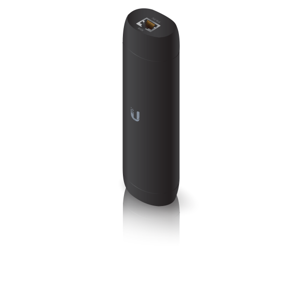
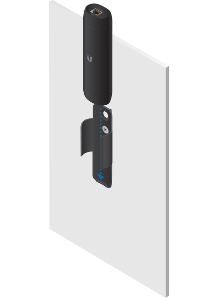
| UniFi Protect ViewPort |
 |
|---|
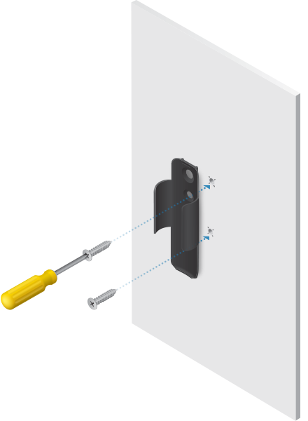
| Mounting Bracket |
 |
|---|
| Double-Sided Tape |
 |
|---|
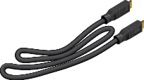
| HDMI Cable |
 |
|---|
| M6 Screw |
 |
|---|
| M8 Screw |
 |
|---|
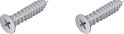
| Drywall Screws (Qty. 2) |
 |
|---|
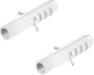
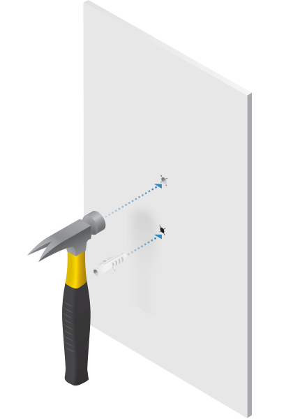
| Screw Anchors (Qty. 2) |
System Requirements
- UniFi Protect Application v1.13 or above, available at ui.com/downloads/unifi
Installation Requirements
- Phillips screwdriver
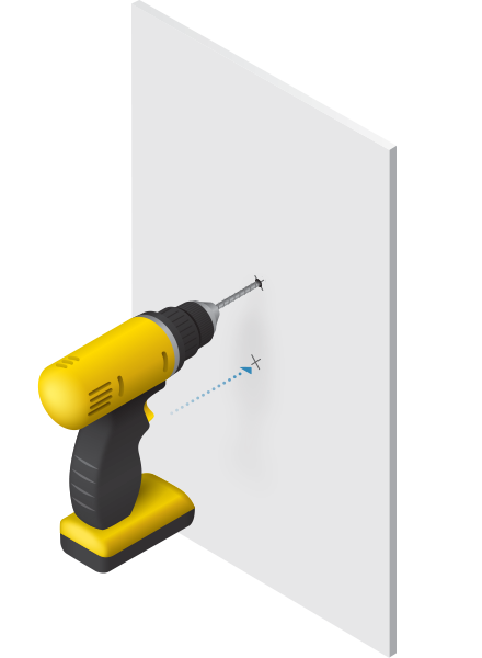
- Drill and 6 mm (1/4") bit for drywall anchors
- Drill and 6 mm (1/4") bit or 8 mm bit (5/16") for screws
- Shielded Category 5 (or above) cabling with drain wire should be used for all wired Ethernet connections and should be grounded through the AC ground of the PoE.
Hardware Overview
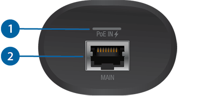

Power/Status LED |
|
|---|---|
Solid White |
Ready for configuration. |
Blue |
The device has been adopted by the UniFi Protect Application. |
Alternating Blue/White |
The device is booting up. |

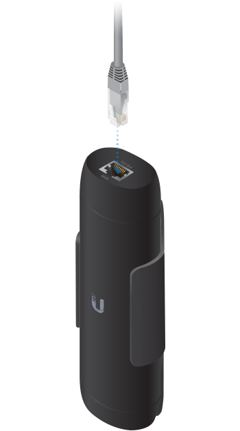
Main Port |
|
This 10/100/1000 RJ45 port connects to an 802.3af switch for PoE power and data. |
|

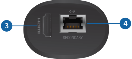
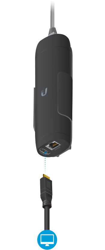
HDMI Port |
|
This HDMI port connects to a TV or monitor with an HDMI cable. It supports 1080p and 4K displays. |
|

Secondary Port |
|
This 10/100/1000 RJ45 port functions as a data passthrough port. |
|

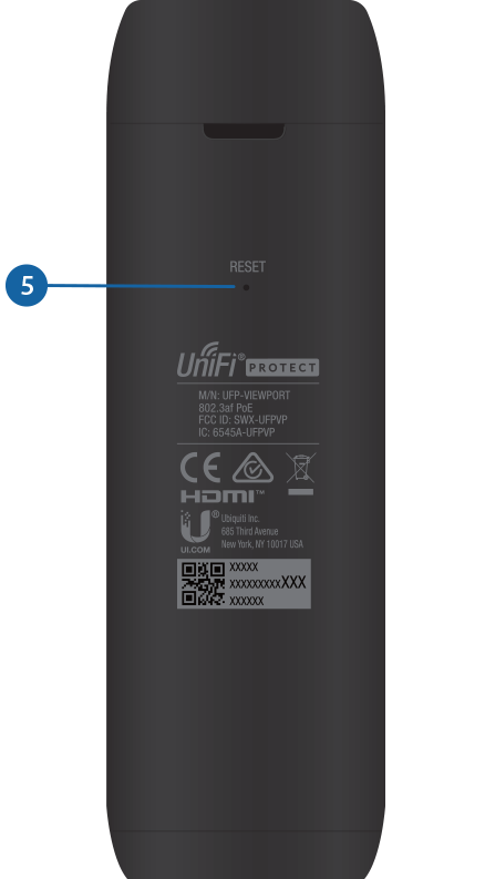
Reset Button |
|
Restore to Factory Defaults Press and hold the Reset button for 5 seconds while the device is powered on. Release the Reset button when the LED turns off. |
|
Hardware Installation
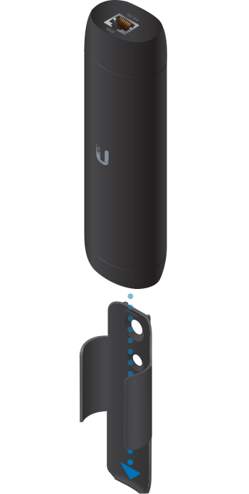
Mounting the UniFi Protect ViewPort is optional; it allows the device to be installed in an inconspicuous and safe location. You have three options for mounting:
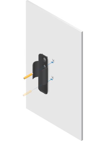
- Wall Mount Mount the ViewPort onto a drywall surface.
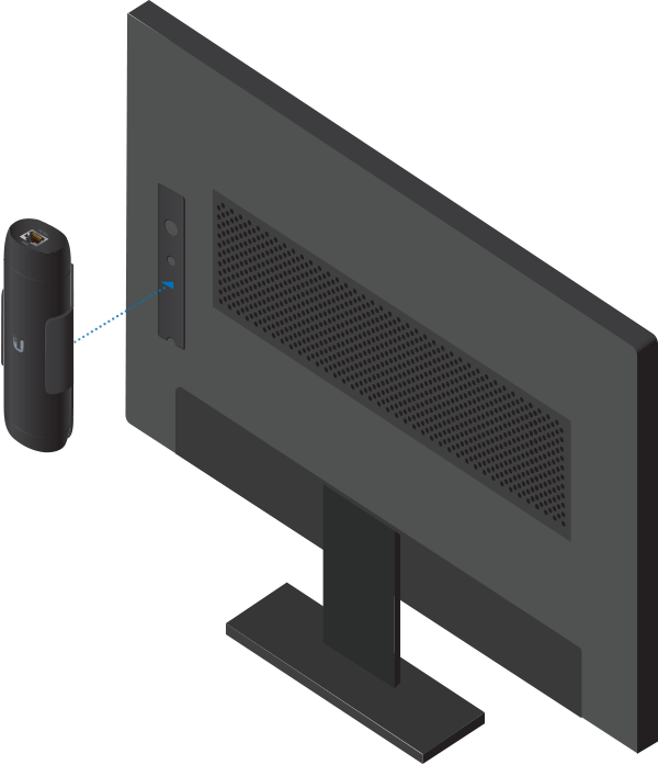
- TV VESA Mount Mount the ViewPort to the back of your TV/monitor using the available VESA mounting hole(s).
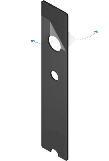
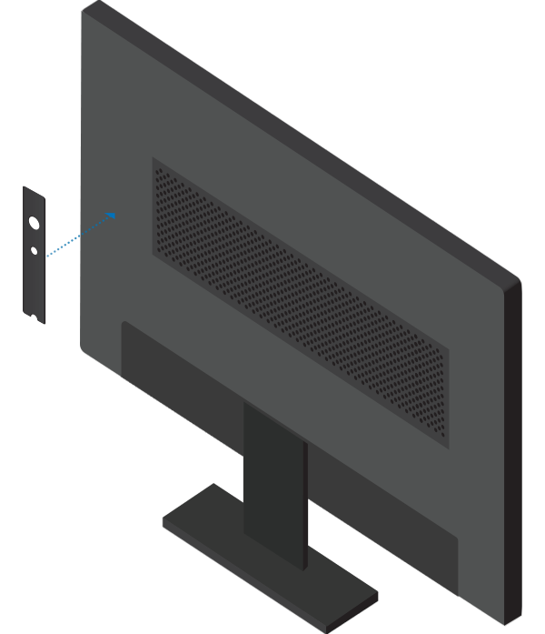
- TV Surface Mount Attach the ViewPort to the TV/monitor or other surface using the included double-sided tape.
Wall Mount
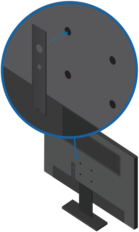
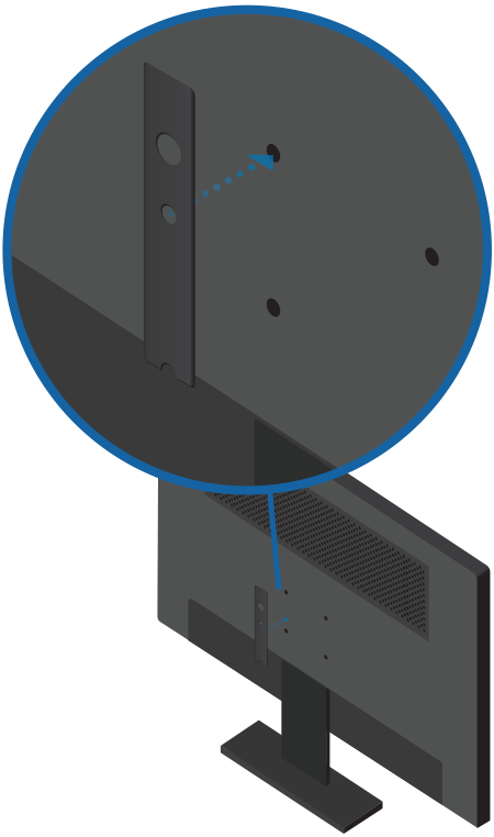
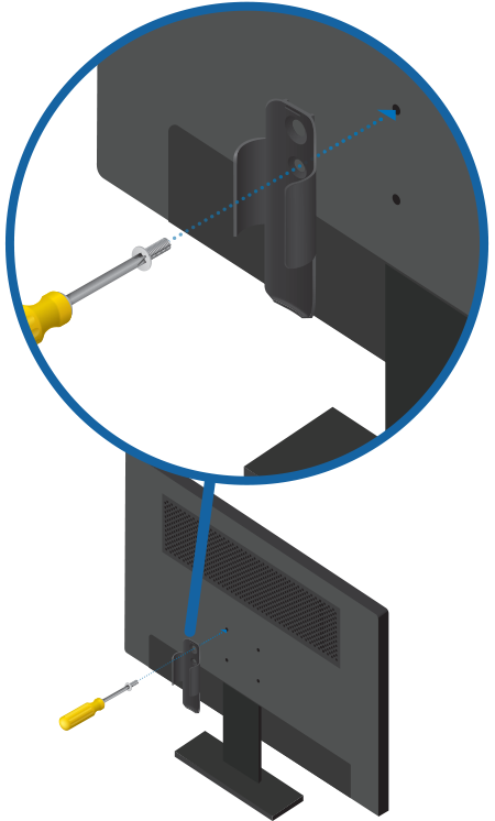
TV VESA Mount
You can use this option if your TV or monitor is equipped with a VESA mount that uses M6 or M8 screws.
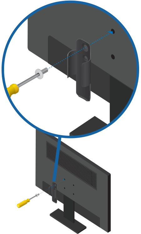
Optional
(for permanent mounting)
| OR |
|
M8 Screw | M6 Screw |
| OR |
|
M8 Screw | M6 Screw |
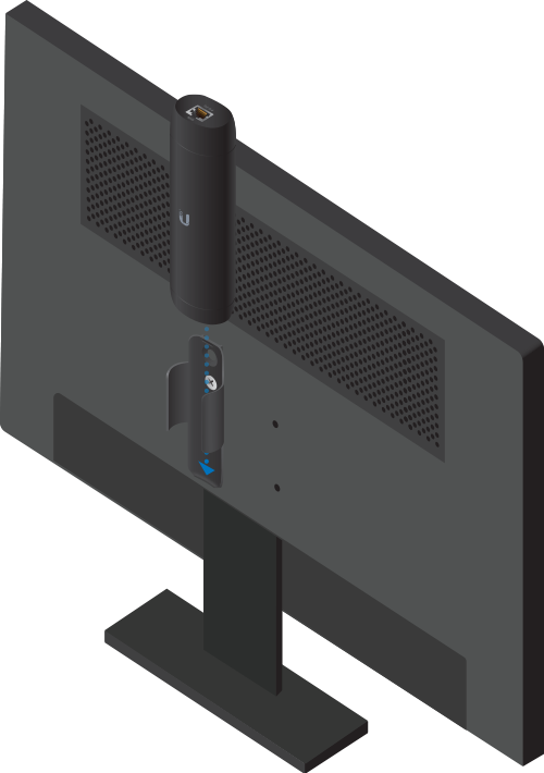
TV Surface Mount
Connecting the ViewPort
- Follow the instructions on the TV or monitor. (If nothing is displayed, check the power source to the device.)
- Log in to UniFi Protect. Enter the UniFi Protect username and password. Then click Submit.
- When UniFi Protect detects the ViewPort, click Add Device.
| WARNING: The switch port must comply with the power specifications listed in “Specifications”. |
|---|

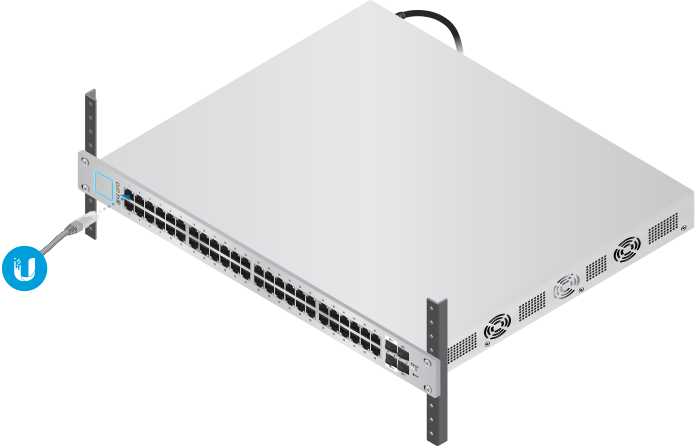
| Note: The PoE switch must be connected to the same LAN or VLAN as the UniFi Protect Application. |
|---|

Specifications
|
UFP-VIEWPORT |
|
|
Dimensions (With TV Mount) |
156.9 x 52 x 37.35 mm (6.18 x 2.0 x 1.47") |
|---|---|
|
Weight |
|
| Without TV Mount | 230 g (8.11oz) |
| With TV Mount | 252 g (8.89 oz) |
|
Enclosure |
Polycarbonate |
|
Networking Interface |
10/100/1000 Ethernet Port |
|
Management Interface |
UniFi Protect Application |
|
Max. Power Consumption |
9.5W |
|
Power Method |
802.3af PoE |
|
Button |
Reset/Factory Reset |
|
LED |
Power/Status |
|
ESD/EMP Protection |
Air: ± 8kV, Contact: ± 4kV |
|
Operating Temperature |
0 to 40° C (32 to 104° F) |
|
Operating Humidity |
20 to 80% Noncondensing |
|
Certifications |
CE, FCC, IC |
Safety Notices
- Read, follow, and keep these instructions.
- Heed all warnings.
- Only use attachments/accessories specified by the manufacturer.
| WARNING: Do not use this product in location that can be submerged by water. |
|---|

| WARNING: Avoid using this product during an electrical storm. There may be a remote risk of electric shock from lightning. |
|---|
Electrical Safety Information
- Compliance is required with respect to voltage, frequency, and current requirements indicated on the manufacturer’s label. Connection to a different power source than those specified may result in improper operation, damage to the equipment or pose a fire hazard if the limitations are not followed.
- There are no operator serviceable parts inside this equipment. Service should be provided only by a qualified service technician.
Limited Warranty
The limited warranty requires the use of arbitration to resolve disputes on an individual basis, and, where applicable, specify arbitration instead of jury trials or class actions.
Compliance
FCC
Changes or modifications not expressly approved by the party responsible for compliance could void the user’s authority to operate the equipment.
This device complies with Part 15 of the FCC Rules. Operation is subject to the following two conditions.
- This device may not cause harmful interference, and
- This device must accept any interference received, including interference that may cause undesired operation.
This equipment has been tested and found to comply with the limits for a Class B digital device, pursuant to Part 15 of the FCC Rules. These limits are designed to provide reasonable protection against harmful interference in a residential installation. This equipment generates, uses, and can radiate radio frequency energy and, if not installed and used in accordance with the instructions, may cause harmful interference to radio communications. However, there is no guarantee that interference will not occur in a particular installation. If this equipment does cause harmful interference to radio or television reception, which can be determined by turning the equipment off and on, the user is encouraged to try to correct the interference by one or more of the following measures:
- Reorient or relocate the receiving antenna.
- Increase the separation between the equipment and receiver.
- Connect the equipment into an outlet on a circuit different from that to which the receiver is connected.
- Consult the dealer or an experienced radio/TV technician for help.
This radio transmitter (FCC ID: SWX-UFPVP) has been approved by FCC.
ISED Canada
CAN ICES-3(B)/NMB-3(B)
This device complies with ISED Canada licence-exempt RSS standard(s). Operation is subject to the following two conditions:
- This device may not cause interference, and
- This device must accept any interference, including interference that may cause undesired operation of the device.
This radio transmitter (IC: 6545A-UFPVP) has been approved by ISED Canada.
CAN ICES-3(B)/NMB-3(B)
Le présent appareil est conforme aux CNR d’ISDE Canada applicables aux appareils radio exempts de licence. L’exploitation est autorisée aux deux conditions suivantes :
- l’appareil ne doit pas produire de brouillage;
- l’appareil doit accepter tout brouillage radioélectrique subi, même si le brouillage est susceptible d’en compromettre le fonctionnement.
Le présent émetteur radio (IC : 6545A-UFPVP) a été approuvé par ISDE Canada.
IMPORTANT NOTE:
Radiation Exposure Statement:
- This equipment complies with radiation exposure limits set forth for an uncontrolled environment.
- This equipment should be installed and operated with minimum distance 20 cm between the radiator and your body.
- This transmitter must not be co-located or operating in conjunction with any other antenna or transmitter.
AVIS IMPORTANT :
Déclaration sur l’exposition aux rayonnements :
- Cet équipement est conforme aux limites prévues pour l’exposition aux rayonnements dans un environnement non contrôlé.
- Lors de l’installation et de la mise en fonctionnement de l’équipement, assurez-vous qu’il y ait une distance minimale de 20 cm entre l’élément rayonnant et vous.
- Cet émetteur ne doit être installé à proximité d’aucune autre antenne ni d’aucun autre émetteur, et ne doit être utilisé conjointement à aucun autre de ces appareils.
Australia and New Zealand

Brazil
| Nota: Este equipamento não tem direito à proteção contra interferência prejudicial e não pode causar interferência em sistemas devidamente autorizados. |
|---|

CE Marking
CE marking on this product represents the product is in compliance with all directives that are applicable to it.
![]()
Country List | ||||||||||||||||||||||||||||||||
| ||||||||||||||||||||||||||||||||
BFWA (Broadband Fixed Wireless Access) members noted in blue |
| Note: This device meets Max. TX power limit per ETSI regulations. |
|---|