Package Contents
 |
|---|
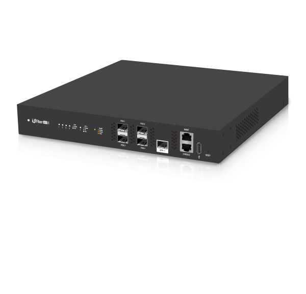
| UFiber OLT-4 |
 |
|---|
| SC/UPC GPON SFP Transceiver (UF‑GP‑B+) |
 |
|---|
| Mounting Brackets (Qty. 2) |
 |
|---|
| Bracket Screws (Qty. 8) |
 |
|---|
| Mounting Screws (Qty. 4) |
 |
|---|
| Cage Nuts (Qty. 4) |
 |
|---|
| Power Cord |
 |
|---|
| Rubber Feet (Qty. 4) |
System Requirements
- Linux, Mac OS X, or Microsoft Windows 7/8/10
- Web Browser: Google Chrome (Other browsers may have limited functionality)
Installation Requirements
- Phillips screwdriver (for rack- or wall-mounting)
- Standard-sized, 19" wide rack with a minimum of 1U height available (for rack-mounting)
- Compatible PON SFP and SFP+ transceivers with appropriate fiber optic cabling and accessories. For information about compatible fiber transceivers, visit:
ubnt.link/UFiber-OLT-Modules
Before You Begin
Designing your first GPON deployment requires specific knowledge and planning. For information on GPON network design and installation, including important considerations and best practices, refer to:
For details on configuring UFiber devices for the first time to allow ONU LAN ports to provide connectivity, refer to: ubnt.link/UFiber-Initial-Configuration
Hardware Overview
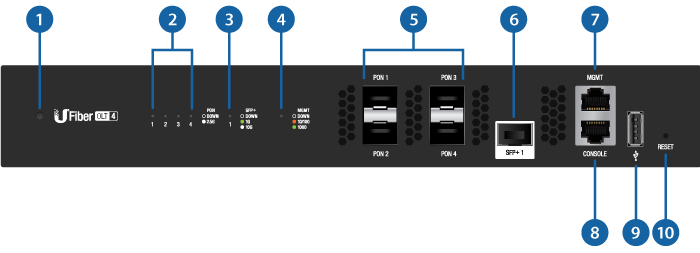

System LED |
|||
|---|---|---|---|
Blue/Flashing |
Initializing/Booting Up |
||
White |
Ready for Use |
||

PON LED (Ports 1 - 4) |
|||
Off |
No Link |
||
White/Flashing |
GPON Link/Activity |
||

SFP+ LED (Port 1) |
|||
Off |
No Link |
||
Green/Flashing |
1G Link/Activity |
||
White/Flashing |
10G Link/Activity |
||

MGMT LED |
|||
Off |
No Link |
||
Amber/Flashing |
10/100 Link/Activity |
||
Green/Flashing |
1000 Link/Activity |
||

GPON (Ports (PON 1- 4) |
|||
Gigabit Passive Optical Network ports support up to 128 clients on each port. |
|||

SFP+ (Port 1) |
|||
Hot-swappable SFP+ port supports 1G or 10G connections. |
|||

MGMT Port |
|||
10/100/1000 Ethernet port used for out‑of‑band management. For firmware version 4.1 and newer, it is set to DHCP Client with the fallback IP address, 192.168.1.20/24.
|
|||

Console Port |
|||
RJ45 serial console port for Command Line Interface (CLI) management. Use an RJ45-to-DB9, serial console cable, also known as a rollover cable, to connect the Console port to your computer. (If your computer does not have a DB9 port, then you will also need a DB9 adapter.) Then configure the following settings as needed:
|
|||

USB Port |
|||
Reserved for future use. |
|||

Reset Button |
|||
There are two methods to reset the device to factory defaults:
|
|||

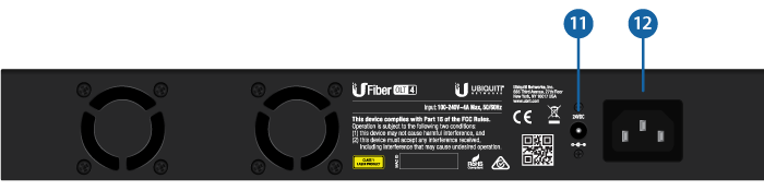
DC Power Jack |
|||
The 24VDC input can connect a redundant or stand-alone DC power source (not included) with minimum power: 56W, 25 to 16V, and 2.5 mm DC power inline connector.
|
|||

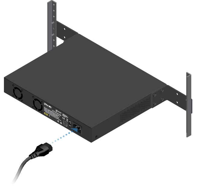
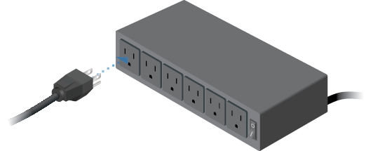
Power |
|||
Connect the included Power Cord to the Power port. |
|||

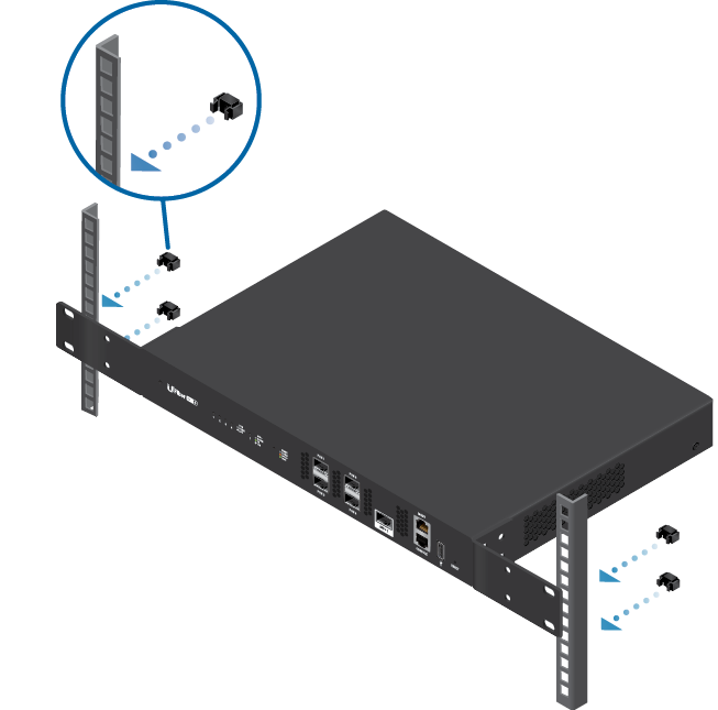
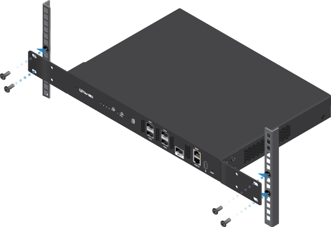
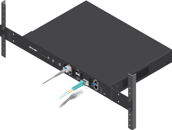
Hardware Installation
Mounting
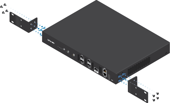
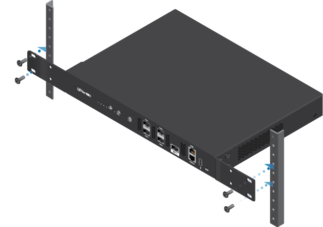
OR
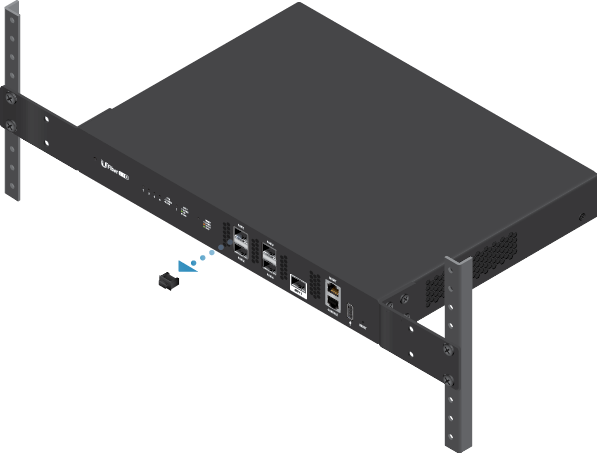
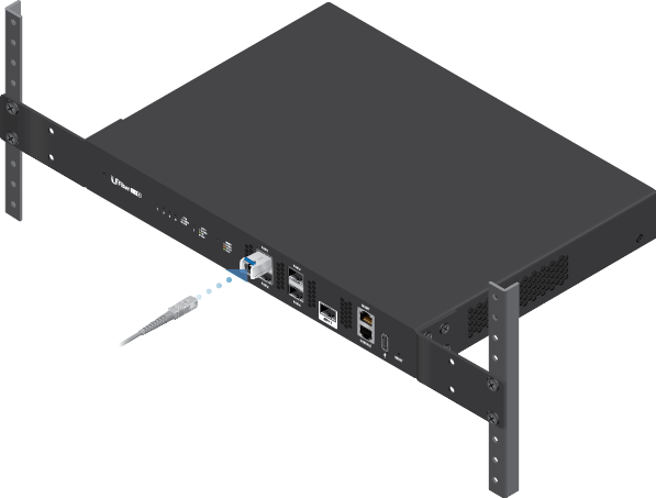
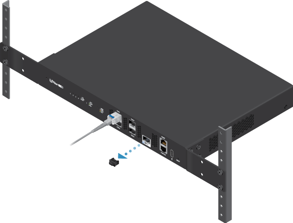
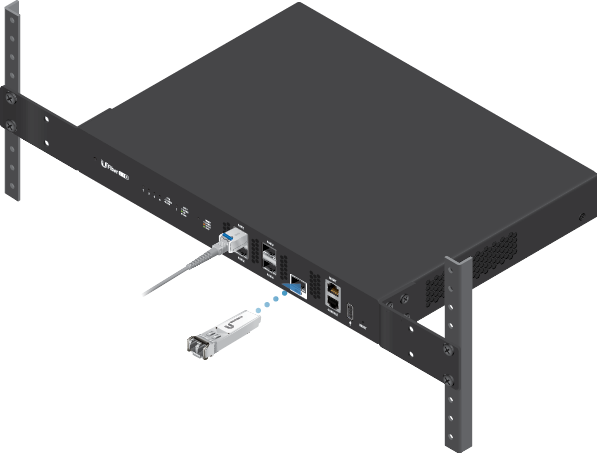
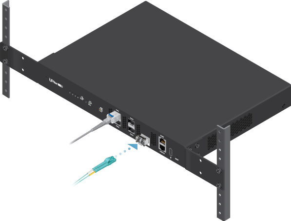
Connecting a PON Module
|
|
WARNING: Never look directly into the ends of fiber or modules. The emitted light could cause damage to the eye. |
|---|

|
|
WARNING: Until ready for use, keep modules and fiber patch cables covered using the included protective caps to ensure the connections stay clean. |
|---|
|
|
Note: One GPON SFP transceiver (model UF-GP-B+) is included. Use a compatible PON SFP transceiver with the appropriate fiber optic cabling for each PON port. For information on compatible fiber transceivers, visit: ubnt.link/UFiber-OLT-Modules |
|---|
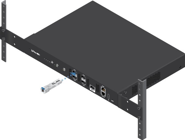
Connecting SFP+
Accessing the Configuration Interface
The following instructions apply to firmware version 4.1 and newer.
|
Note: Previous firmware versions default to a static IP: 192.168.1.1. |
|---|
- Connect an Ethernet cable from the MGMT port on the device to a LAN segment that has an existing DHCP server.
- To check the IP address of the device, use one of the following methods:
- Set up the DHCP server to provide a specific IP address to the device based on its MAC address (on the label).
- Let the device obtain an IP address and then check the DHCP server to see which IP address was assigned.
- Launch your web browser. Enter the appropriate IP address in the address field. Press enter (PC) or return (Mac).
- Enter ubnt in the Username and Password fields. Click Login.
Customize settings as needed. For more information, refer to the UFiber resources, which are available at: http://ubnt.link/UFiber-Support
Specifications
|
UF-OLT-4 |
|
|
Dimensions |
299.80 x 258.95 x 42.55 mm |
|---|---|
|
Weight |
|
| Without Mount Brackets | 1.93 kg (4.25 lb) |
| With Mount Brackets | 2.13 kg (4.70 lb) |
|
Max. Power Consumption |
35W (Excluding SFP Transceivers) |
|
Power Method |
110 - 240VAC Modular Port |
|
Power Supply |
AC/DC Internal 56W DC |
|
Supported Voltage Range |
100 - 240VAC; 16-25VDC |
|
Button |
Reset |
|
Processor |
MIPS 1004Kc 880 MHz Dual-Core |
|
System Memory |
512 MB DDR3, 512 MB NAND |
| LEDs |
|
| System | Status |
| PON Data Ports | Link/Activity |
| SFP+ Data Ports | Link/Activity |
| RJ45 (MGMT) Port | Link/Activity |
| Interfaces |
|
| Data Ports | (4) GPON OLT |
| Management Port | (1) RJ45 Ethernet Port |
| Serial Console Port | (1) RJ45 Serial Port |
|
Rackmount |
Yes |
|
Operating Temperature |
-10 to 45° C (14 to 113° F) |
|
Operating Humidity |
10 - 90% Noncondensing |
|
Certifications |
CE, FCC, IC |
|
GPON SFP OLT Transceiver |
Single Fiber, SM SC/UPC, 20 km, 1490 nm TX/1310 nm RX, ITU-T G984.2 Class B+ |