Package Contents
 |
|---|
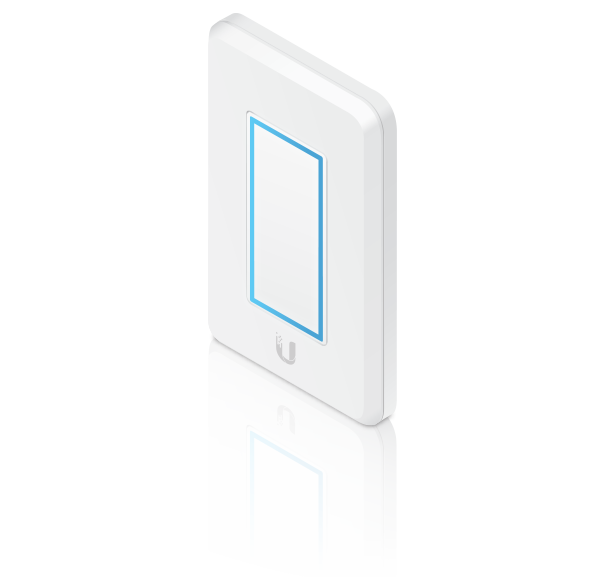
| UniFi Dimmer Switch |
 |
|---|
| Mounting Screws (Qty. 2) |
System Requirements
- An 802.3af-compliant network switch
- UniFi Connect Mobile app
- Mobile device: iOS 10 or Android™ 5.0
- UniFi Connect Application:
- Computer: UniFi Application Server 0.5.0, Ubuntu 16.04 LTS (Xenial Xerus) 64-bit, or Debian 9 64-bit
- Web browser: Google Chrome (Other browsers may have limited functionality.)
Hardware Overview
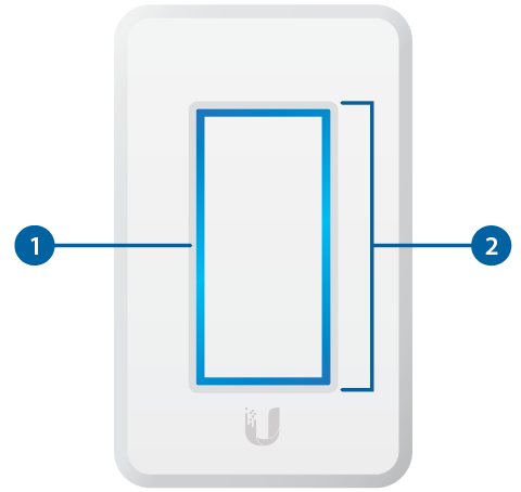

LED |
|
|---|---|
Flashing White |
Initializing. |
Breathing White |
System ready. |
Alternating White/Blue |
Firmware upgrade is taking place. |
Breathing Blue |
Adopted by the Connect Application. |
Flashing Blue |
This is used to locate a UniFi Dimmer Switch. When you click Locate in the UniFi Coonect Application or UniFi Connect Mobile app, the UniFi Dimmer Switch LED will flash. |

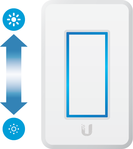
Touch Pad |
|
Once the UniFi Dimmer Switch is paired with the UniFi LED Panel, you can use the UniFi Dimmer Switch’s Touch Pad to turn the LED Panel on and off and to control its brightness:
|
|

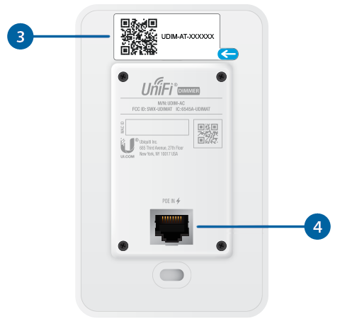
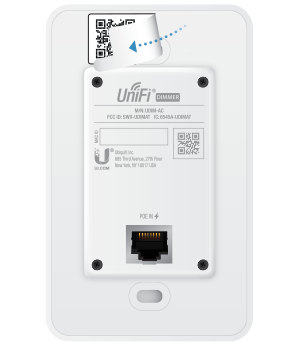
MAC Sticker |
|
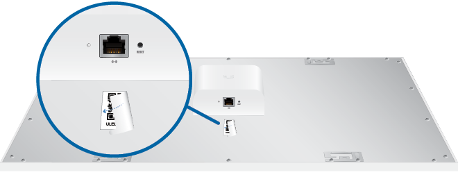
Used to scan the MAC address. For details, refer to “Quick Setup”. |
|

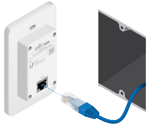
PoE + Data |
|
This 10/100 Ethernet port supports data and 802.3af PoE. Connect this port to a UniFi Switch with PoE that is connected to your LAN and DHCP server. |
|

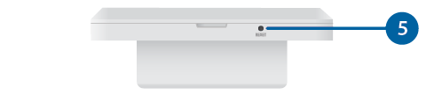
Reset |
|
The Reset button serves two functions:
|
|
Hardware Installation
An electrical wall box should be pre-installed with an Ethernet cable running from the box to a UniFi Switch with 802.3af PoE.
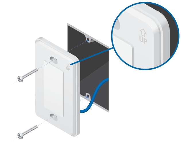
| WARNING: To avoid damage, use ONLY the included Mounting Screws or #6-32x26 truss head machine screws (maximum head diameter: 8 mm). Do NOT over-tighten the screws. |
|---|

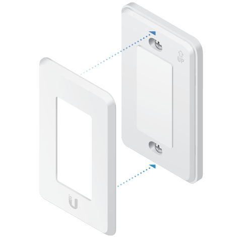
The UniFi Dimmer Switch is Plug and Play; by default, it will be paired automatically with all UniFi LED Panels on the same Layer 2 network.
|
|
Note: For best results:
|
|---|

Quick Setup
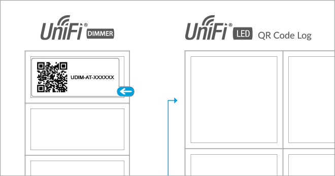
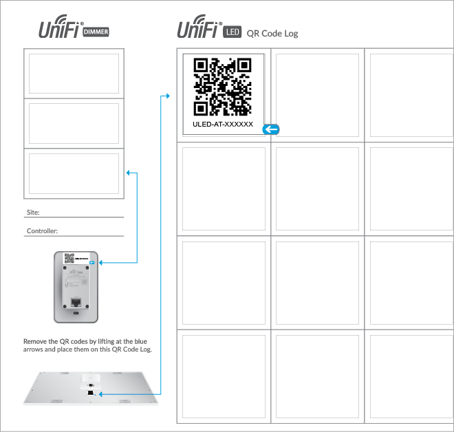
This section describes the Quick Setup procedure for installations with large numbers of UniFi LED Panels and Dimmer Switches. The Quick Setup requires using the UniFi LED app along with a QR Code Log that you create. Each UniFi LED Panel or Dimmer Switch has a removable MAC Sticker on its reverse side; this has a QR code used to scan the device’s MAC address. The Quick Setup consists of these steps:
- Create the QR Code Log
- Install the LED Panels and Dimmer Switches
- Scan the QR codes
Create the QR Code Log
- Download the QR Code Log template at: ubnt.link/QR-Code-Log
- Print out as many copies as needed (each sheet can log up to 16 LED Panels and 3 Dimmer Switches).
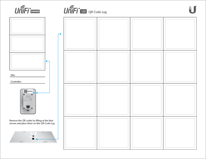
- Fill in the Site (such as “1st Floor Meeting Room”) and OS Console (such as “UniFi Connect Application”) on each sheet.
Install the LED Panels and Dimmer Switches
For each device:
- Install the device as decribed in the Installation section of the device’s Quick Start Guide.
OR
OR
Specifications
|
UDIM-AT |
|
|
Dimensions |
71 x 115 x 25 mm |
|---|---|
|
Weight |
90 g (3.17 oz) |
|
Management Interface |
UniFi Connect Application UniFi Connect Mobile App |
|
Networking Interface |
10/100 Mbps Ethernet Port |
|
Buttons |
Reset |
|
Power Method |
802.3af PoE |
|
Power Supply |
Standard 802.3af PoE |
|
Supported Voltage Range |
48V |
|
Max. Power Consumption |
5W |
|
Operating Temperature |
0 to 40° C (32 to 104° F) |
|
Certifications |
FCC, IC |