Package Contents
 |
|---|
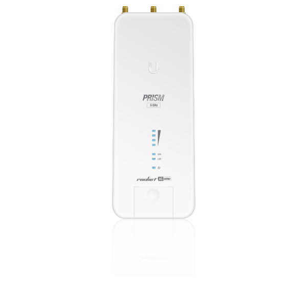
| Rocket Prism 5AC |
 |
|---|
| GPS Antenna |
 |
|---|
| Gigabit PoE (24V, 1A) with Mounting Bracket |
 |
|---|
| Power Cord |
Installation Requirements
- The GPS Antenna needs to have clear line of sight to the sky for proper GPS operation.
- Shielded Category 5 (or above) cabling with drain wire should be used for all wired Ethernet connections and should be grounded through the AC ground of the PoE.
We recommend that you protect your networks from harmful outdoor environments and destructive ESD events with industrial-grade, shielded Ethernet cable from Ubiquiti. For more details, visit ui.com/toughcable
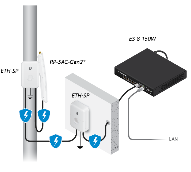
- Surge protection should be used for all outdoor installations. We recommend that you use two Ethernet Surge Protectors, model ETH-SP, one near the RocketPrism and the other at the entry point to the building. The ETH-SP will absorb power surges and safely discharge them into the ground.
* Shown without the antenna.
Hardware Overview
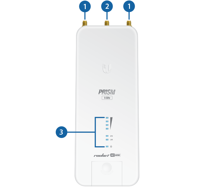

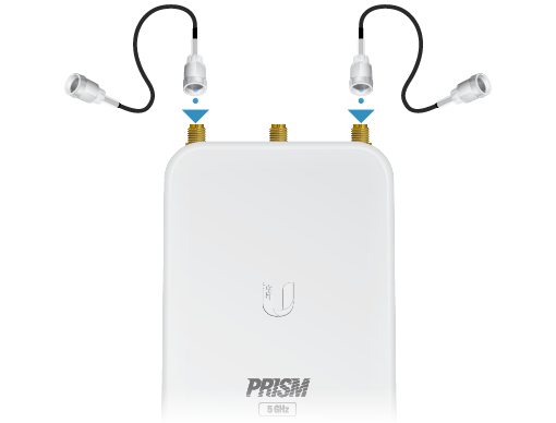
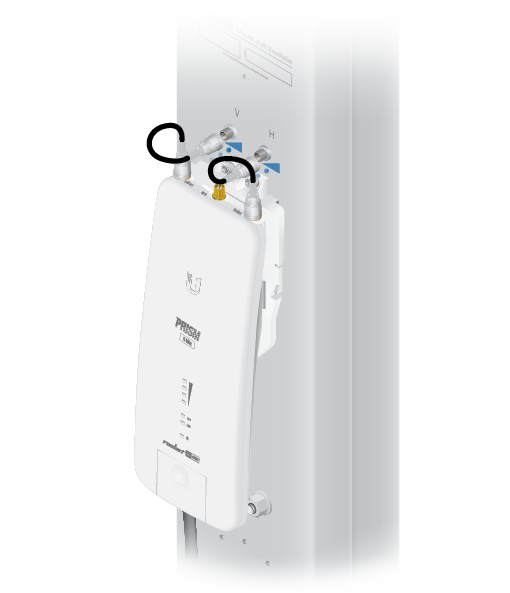
RP-SMA Antenna Connectors |
|---|
Used to attach RF cables (not included). |

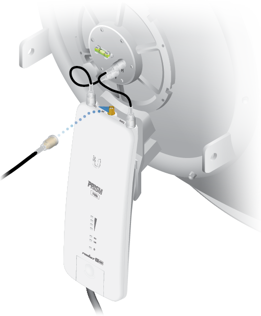
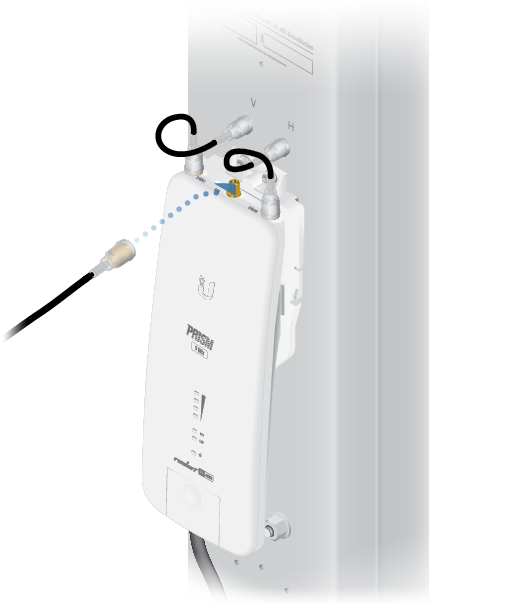
GPS Antenna Connector |
Used to attach the GPS Antenna. |

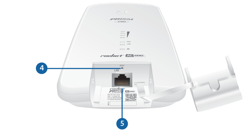
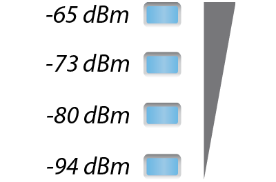
LEDs |
Signal In airOS®, you can modify the wireless signal strength threshold values for each LED on the Wireless tab under Signal LED Thresholds. Each LED will light when the wireless signal strength is equal to or greater than the LED’s threshold value. The default values are shown below:
GPS The GPS LED will light steady blue when the GPS signal strength is sufficient. This requires a minimum of three satellite connections. LAN The LAN LED will light steady blue when an active Ethernet connection is made to the LAN port and flash when there is activity. Power The Power LED will light blue when the device is connected to a power source. |
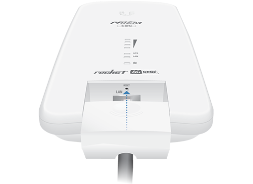
 Reset Button |
To reset to factory defaults, press and hold the Reset button for more than 10 seconds while the device is already powered on. Alternatively, the device may be reset remotely via a Reset button located on the bottom of the Gigabit PoE adapter. |

LAN |
The Gigabit Ethernet port is used to connect the power and should be connected to the LAN and DHCP server. |
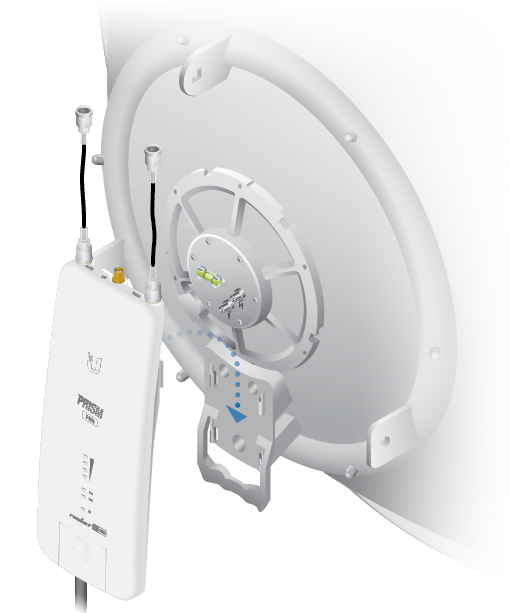
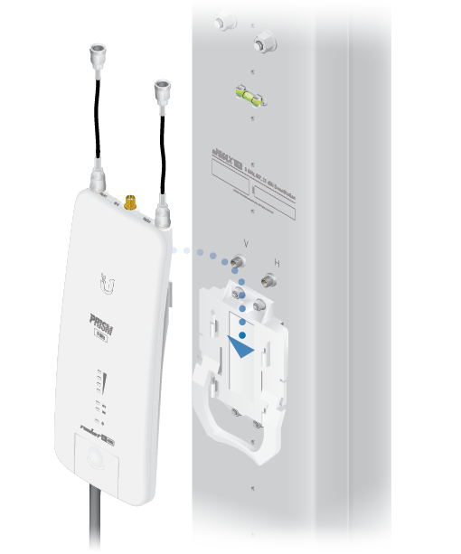
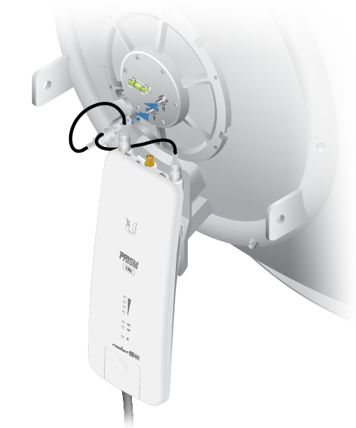
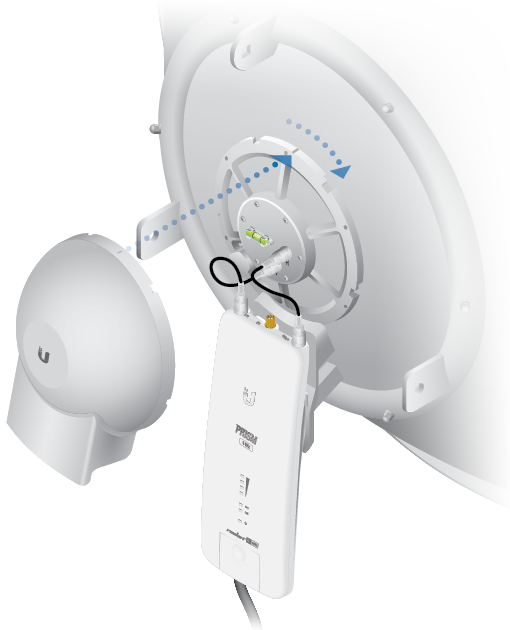
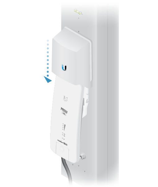
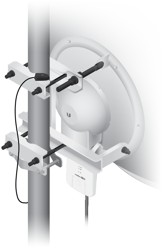
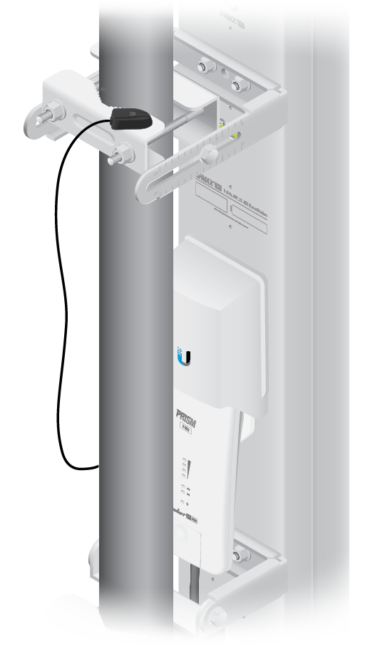
Hardware Installation
The Rocket is designed to mount directly onto a Ubiquiti airMAX RocketDish™ antenna for Point-to-Point use or an airMAX Sector antenna for Point-to-MultiPoint use.
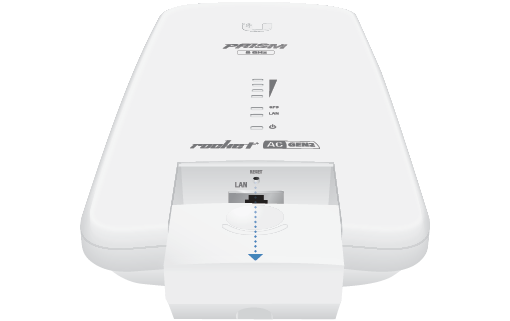
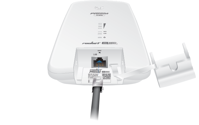
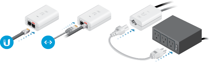
- Connect the power using:
OR
OR
OR
OR
OR
- included Gigabit PoE Adapter
- PoE switch
| WARNING: The switch port must comply with the power specifications listed in this Quick Start Guide. |
|---|

Accessing airOS via Wi-Fi
Installer Compliance Responsibility
Devices must be professionally installed and it is the professional installer’s responsibility to make sure the device is operated within local country regulatory requirements.
Antenna
Select your antenna from the list. If Calculate EIRP Limit is enabled, transmit output power is automatically adjusted to comply with the regulations of the applicable country. For a Custom antenna, Antenna Gain is entered manually. Note the requirements and antenna types listed below.
Cable Loss (When applicable)
Enter the cable loss in dB. Output power is adjusted to compensate for loss between the radio and the antenna.
Certified Antenna Types
This radio transmitter FCC ID: SWX-RP5ACG2 / IC: 6545A-RP5ACG2 has been approved by FCC / ISED Canada to operate with the antenna types listed below with the maximum permissible gain for each antenna type indicated. Antenna types not included in this list or having a gain greater than the maximum gain indicated for that type, are strictly prohibited for use with this device.
|
Antenna |
Frequency |
Gain |
|---|---|---|
|
Omni |
5 GHz |
13 dBi |
|
Sector |
5 GHz |
22 dBi |
|
Dish |
5 GHz |
34 dBi |
Specifications
|
RP-5AC-Gen2 |
|
|
Dimensions |
88 x 40 x 230 mm (3.47 x 1.58 x 9.06") |
|---|---|
|
Weight |
400 g (14.11 oz) |
|
Networking Interface |
(1) 10/100/1000 Ethernet Port |
|
RF Connectors |
(2) RP-SMA (Waterproof) |
|
LEDs |
(4) Signal Strength, GPS, Power, LAN |
|
Enclosure |
Die-Cast Aluminum with |
|
Max. Power Consumption |
9.5W |
|
Power Supply |
24V, 1A Gigabit PoE Adapter (Included) |
|
Power Method |
Passive PoE (Pairs 4, 5+; 7, 8 Return) |
|
Processor |
MIPS 74Kc |
|
Memory |
128 MB DDR2 SDRAM |
|
Operating Temperature |
-40 to 80° C (-40 to 176° F) |
|
Operating Humidity |
5 to 95% Noncondensing |
|
ESD/EMP Protection |
± 24KV Contact / Air for Ethernet |
|
Shock and Vibrations |
ETSI300-019-1.4 |
|
Certifications |
CE, FCC, IC |
|
Operating Frequency (MHz) |
||
|
Worldwide |
5150 - 5875 |
|
|---|---|---|
|
US/CA |
U-NII-1 |
5150 - 5250 |
|
U-NII-2A |
5250 - 5350 | |
|
U-NII-2C |
5470 - 5725 | |
|
U-NII-3 |
5725 - 5850 |
|
|
Management Radio (MHz) |
|
|
Worldwide |
2412 - 2472 |
|---|---|
|
US/CA |
2412 - 2462 |