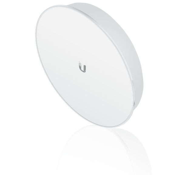
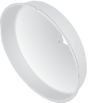
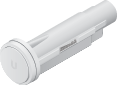
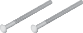
Package Contents
 |
|---|
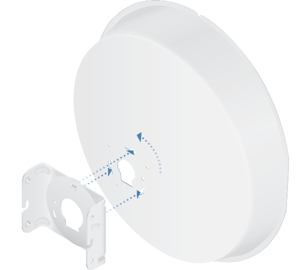
| Reflector |
 |
|---|
| Radome |
 |
|---|
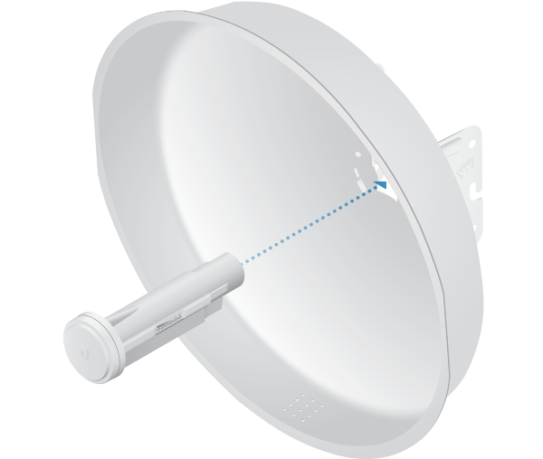
| Antenna Feed* |
 |
|---|
| Rear Housing |
 |
|---|
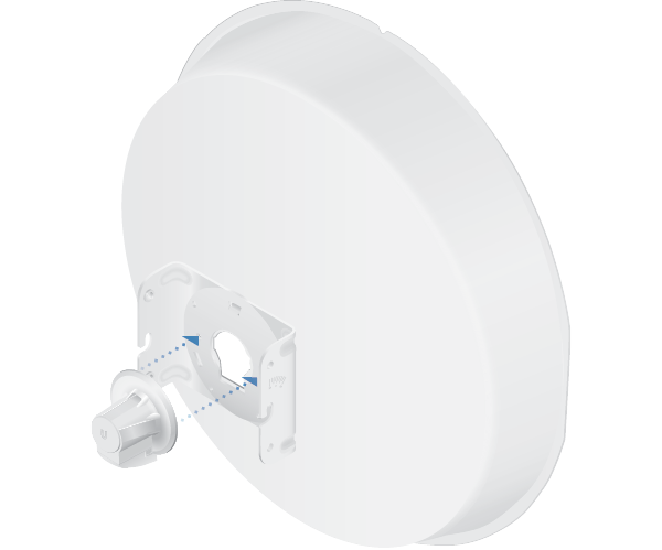
| Mounting Bracket |
 |
|---|
| Adjustment Bracket |
 |
|---|
| Hex Bolts with Washers (Qty. 4) |
 |
|---|
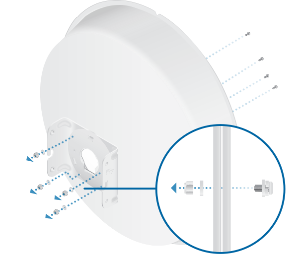
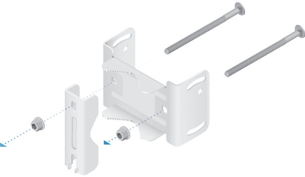
| Pole Clamp |
 |
|---|
| Carriage Bolts (Qty. 2) |
 |
|---|
| Flange Nuts (Qty. 2) |
 |
|---|
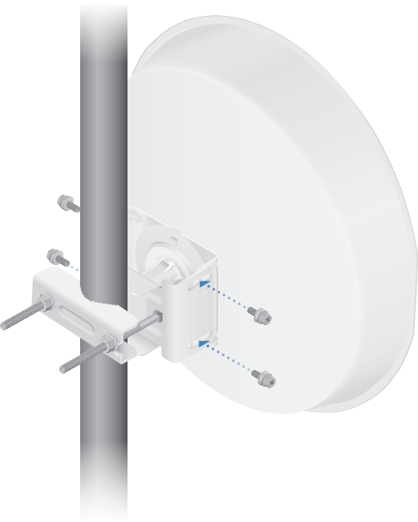
| Screws with Washers (Qty. 4) |
 |
|---|
| Washers (Qty. 4) |
 |
|---|
| Nylon Insert Lock Nuts (Qty. 4) |
 |
|---|
| Gigabit PoE (24V, 0.5A) with Mounting Bracket |
 |
|---|
| Power Cord |
* The PBE-M5-400-ISO Antenna Feed has a thin gray ring around the center of the cap to differentiate it from the PBE-M5-300-ISO Antenna Feed.
Installation Requirements
- 13 mm wrench
- Shielded Category 5 (or above) cabling should be used for all wired Ethernet connections and should be grounded through the AC ground of the PoE.
We recommend that you protect your networks from harmful outdoor environments and destructive ESD events with industrial-grade, shielded Ethernet cable from Ubiquiti. For more details, visit ui.com/toughcable
Hardware Overview
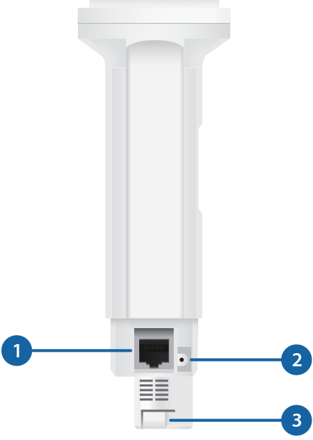
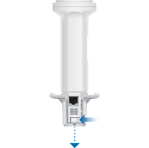
 Ethernet |
|---|
This Gigabit Ethernet port is used to connect the power and should be connected to the LAN and DHCP server. |
 Reset Button |
To reset to factory defaults, press and hold the Reset button for more than 10 seconds while the device is powered on. Alternatively, the device may be reset remotely via a Reset button located on the bottom of the Gigabit PoE adapter. |
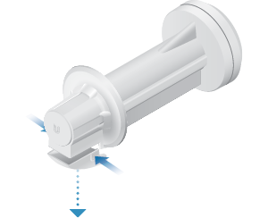
 Release Button |
After you assemble the device, check the Release button; it should be fully engaged in the Release Button Slot of the Rear Housing. This ensures that the Antenna Feed is locked into place. If you need to remove the Antenna Feed, you must depress the Release button first. |
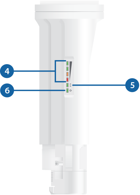
 Signal LEDs |
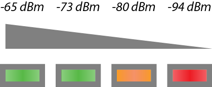
In airOS®, you can modify the threshold values for the wireless signal strength LEDs on the Advanced tab under Signal LED Thresholds. The default values are shown below:
|
 Ethernet LED |
The Ethernet LED will light steady green when an active Ethernet connection is made and flash when there is activity. |
 Power LED |
The Power LED will light green when the device is connected to a power source. |
Application Examples
The PowerBeam mounted outdoors with the Reflector installed provides directional outdoor coverage (gain is reflector-dependent).
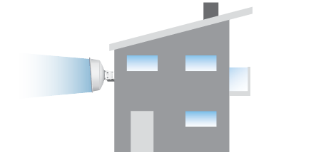
The PowerBeam mounted outdoors without the Reflector installed provides outdoor-to-indoor coverage using the 3 dBi Antenna Feed only.

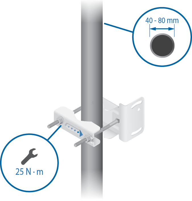
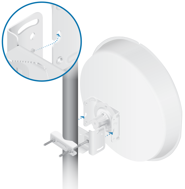
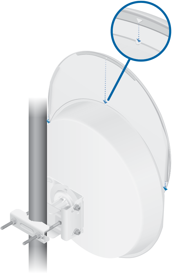
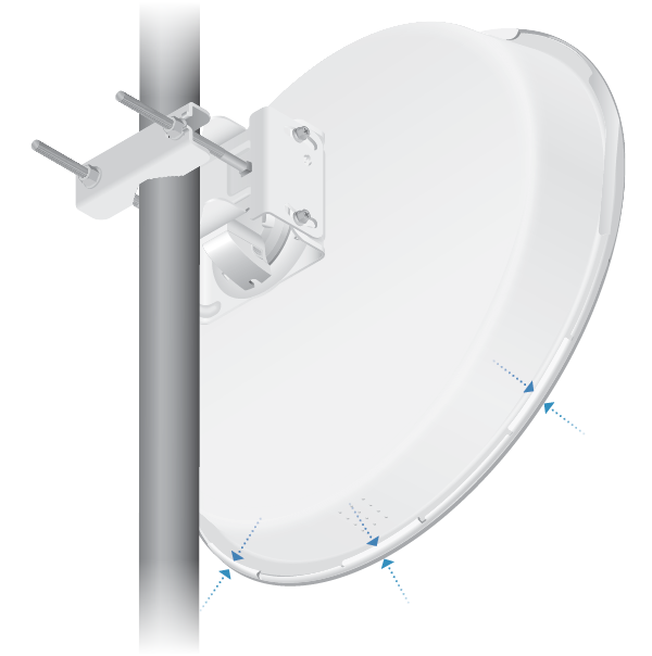
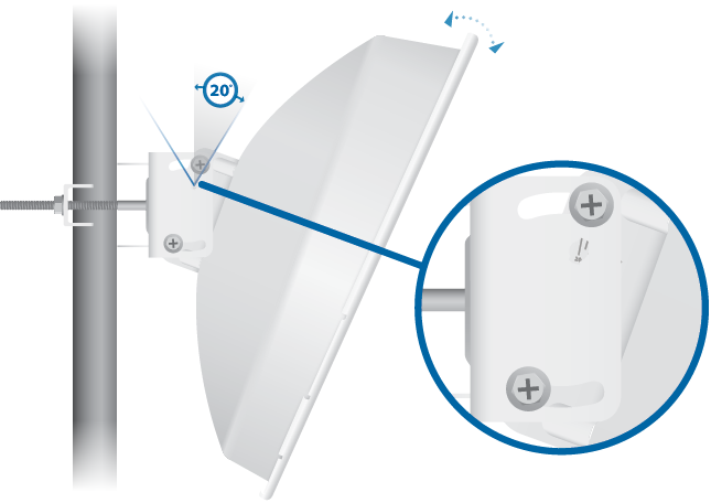
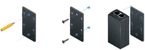
Installation
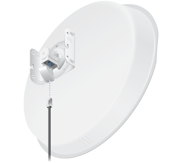
Connecting Power
| WARNING: The switch port must comply with the power specifications listed in this Quick Start Guide. |
|---|

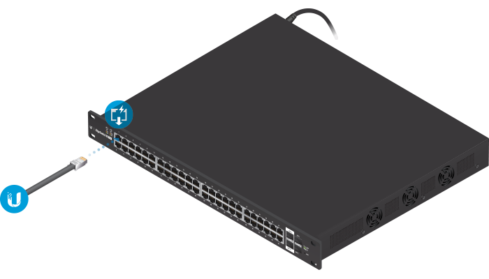
OR
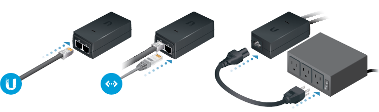
Optional
Accessing airOS
Verify connectivity in the airOS Configuration Interface.
- Make sure that your host system is connected via Ethernet to the device.
- Configure the Ethernet adapter on your host system with a static IP address on the 192.168.1.x subnet.
- Launch your web browser and type https://192.168.1.20 in the address field. Press enter (PC) or return (Mac).

- Enter ubnt in the Username and Password fields. Select your Country and Language. You must agree to the Terms of Use to use the product. Click Login.
The airOS Configuration Interface will appear, allowing you to customize your settings as needed. For details, refer to the User Guide available at ui.com/download/airmax
You can also manage your device using the Ubiquiti Internet Service Provider Application. Setup using the UISP™ app requires the U-Installer, sold separately.
Installer Compliance Responsibility
Devices must be professionally installed and it is the professional installer’s responsibility to make sure the device is operated within local country regulatory requirements.
Antenna
Select your antenna from the list. If Calculate EIRP Limit is enabled, transmit output power is automatically adjusted to comply with the regulations of the applicable country. Note the requirements and antenna types listed below.
Cable Loss (When applicable)
Enter the cable loss in dB. Output power is adjusted to compensate for loss between the radio and the antenna.
Certified Antenna Types
This radio transmitter FCC ID: SWX-PBE5M / IC: 6545A-PBE5M has been approved by FCC / ISED Canada to operate with the antenna types listed below with the maximum permissible gain for each antenna type indicated. Antenna types not included in this list or having a gain greater than the maximum gain indicated for that type, are strictly prohibited for use with this device.
|
Antenna |
Frequency |
Gain |
|---|---|---|
|
Dish |
5 GHz |
25 dBi |
Specifications
|
PBE-M5-400-ISO |
|
|
Dimensions with Radome |
459 x 459 x 261 mm (18.07 x 18.07 x 10.28") |
|---|---|
|
Weight (Mount Included) |
3.22 kg (7.10 lb) |
|
Gain |
25 dBi |
|
Networking Interface |
(1) 10/100/1000 Ethernet Port |
|
Enclosure |
Outdoor UV Stabilized Plastic |
|
Max. Power Consumption |
8W |
|
Max. TX Power |
24 dBm |
|
Power Supply |
24V, 0.5A Gigabit PoE Adapter (Included) |
|
Power Method |
Passive PoE (Pairs 4, 5+; 7, 8 Return) |
|
Wind Survivability |
200 km/h (125 mph) |
|
Wind Loading |
559 N @ 200 km/h (125.7 lbf @ 125 mph) |
|
Mounting |
Pole Mounting Kit Included |
|
Operating Temperature |
-40 to 70° C (-40 to 158° F) |
|
Operating Humidity |
5 to 95% Noncondensing |
|
Shock and Vibrations |
ETSI300-019-1.4 |
|
Certifications |
CE, FCC, IC |
|
Operating Frequency (MHz) |
||
|
Worldwide |
5150 - 5875 |
|
|---|---|---|
|
US/CA |
U-NII-1 |
5150 - 5250 |
|
U-NII-2A |
5250 - 5350 | |
|
U-NII-2C |
5470 - 5725 | |
|
U-NII-3 |
5725 - 5850 |
|