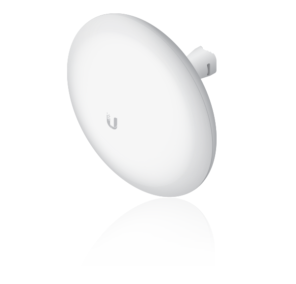
Package Contents
 |
|---|
| GBE |
 |
|---|
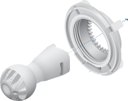
| Ball Joint Mount |
 |
|---|
| Lock Ring |
 |
|---|
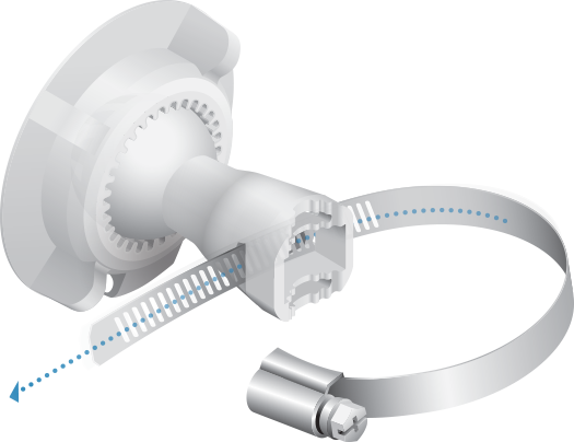
| Metal Strap |
 |
|---|
| Gigabit PoE (24V, 0.5A) with Mounting Bracket |
 |
|---|
| Power Cord |
Installation Requirements
- Clear line of sight between GigaBeam AP and station
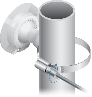
- Pole-mounting: 7 mm socket wrench or screwdriver
- Wall-mounting: wall fastener (not included)
- Shielded Category 5 (or above) cabling with drain wire should be used for all wired Ethernet connections and should be grounded through the AC ground of the PoE.
We recommend that you protect your networks from harmful outdoor environments and destructive ESD events with industrial-grade, shielded Ethernet cable from Ubiquiti. For more details, visit ui.com/toughcable
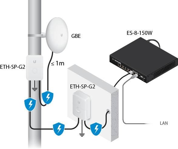
- Surge protection should be used for all outdoor installations. We recommend that you use two Ethernet Surge Protectors, model ETH-SP-G2, one near the device and the other at the entry point to the building. The ETH-SP-G2 will absorb power surges and safely discharge them into the ground.

Note: For guidelines about grounding and lightning protection, follow your local electrical regulatory codes.
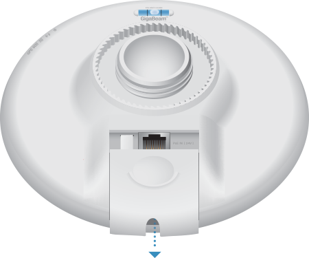
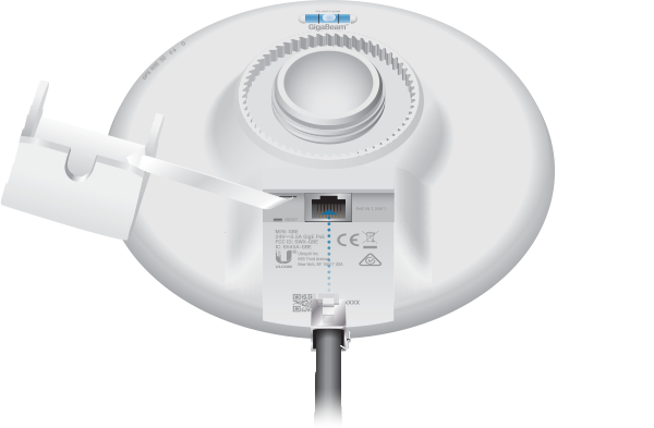
Hardware Overview
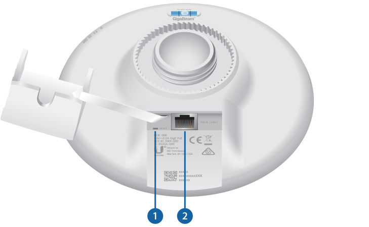

 Reset Button |
|
|---|---|
To reset to factory defaults, press and hold the Reset button for more than 10 seconds while the device is powered on. Alternatively, the device may be reset remotely via a Reset button located on the bottom of the Gigabit PoE Adapter. |
|

PoE IN Port |
|
This Gigabit Ethernet port is used to connect the power and should be connected to the LAN and DHCP server. |
|

60 GHz LED |
|
Lights steady blue when 60 GHz link is ready. |
|

5 GHz LED |
|
Lights steady blue when the 5 GHz link is ready. |
|

LAN LED |
|
The LED will light steady blue when an active Ethernet connection is made to the Ethernet port and flash when there is activity. |
|

Power/Status LED |
|
Flashing White |
Bootup in progress. |
White |
Ready for use, not connected to Ubiquiti Internet Service Provider (UISP™). See “UISP Management”. |
Blue |
Ready for use, connected to UISP. |
Steady Blue with Occasional Flashing |
Ready for use, unable to connect to UISP, check connection to UISP server. |
Quickly Flashing Blue |
Used to locate a device in UISP. |
Alternating |
Firmware upgrade in progress. |
Hardware Installation
Go to the appropriate mounting instructions: Pole Mounting or “Wall Mounting”.
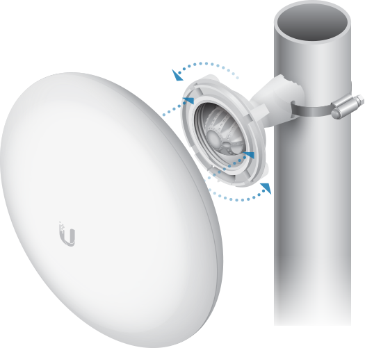
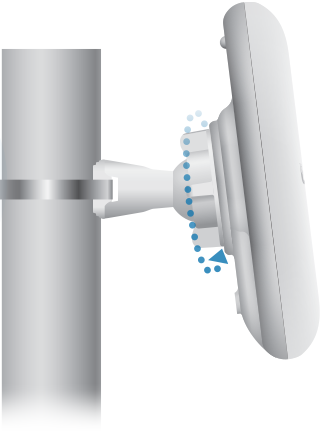
Pole-Mounting
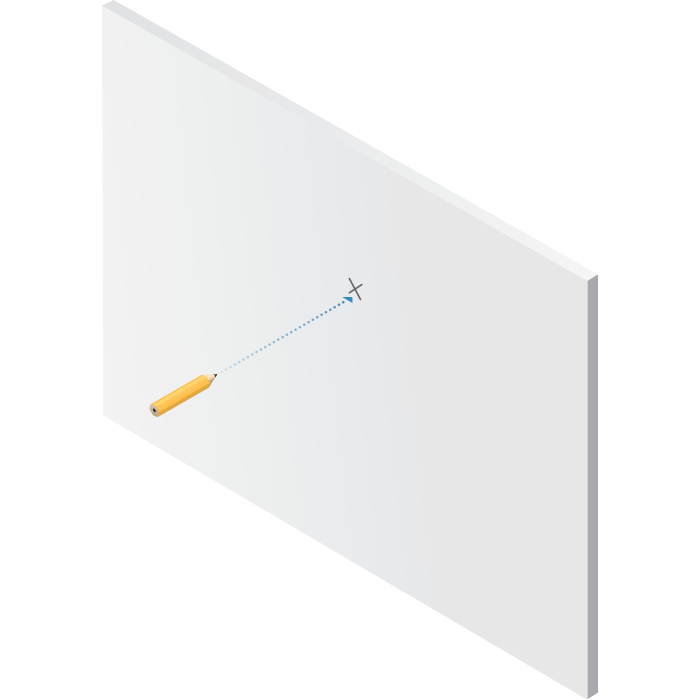
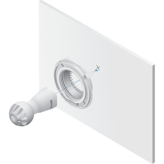
Wall Mounting
The device must be mounted directly to a wood stud or other structurally stable surface to avoid damage to the mounting hole when you adjust the aim.
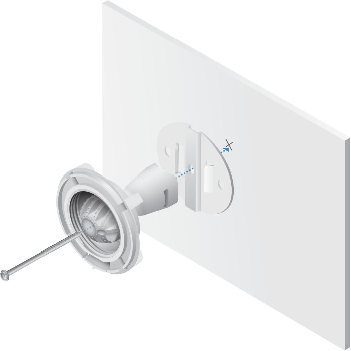
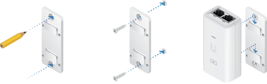
Optional Accessory
To enhance stability, you can use the NanoBeam® Wall Mount Kit, model NBE-WMK (sold separately).

|
|
Note: Center screw included. Two optional screws (not included) provide additional stability. |
|---|
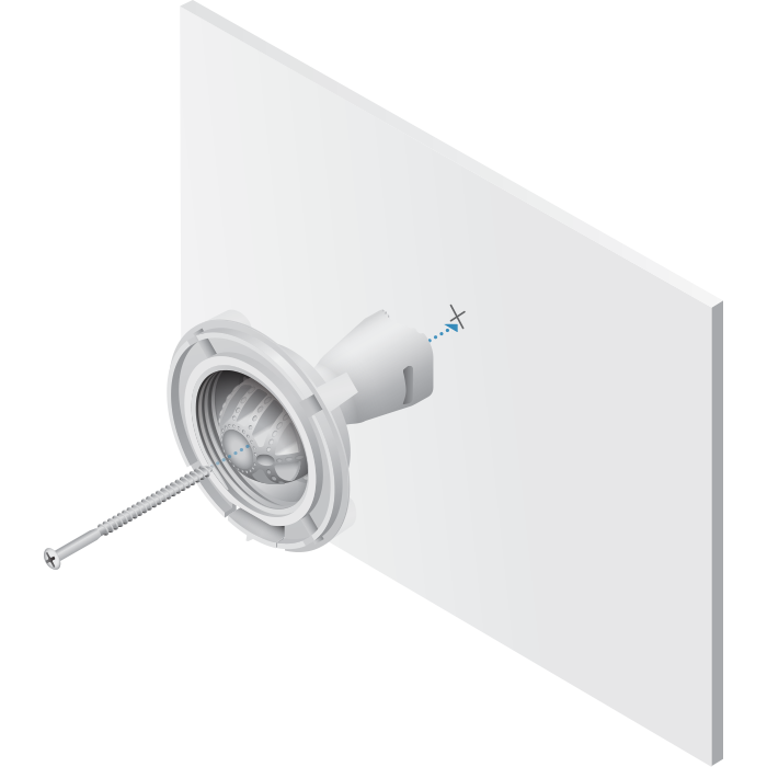
Installation Instructions
Fastener (not included) |
OR |
NanoBeam Wall Mount Kit |
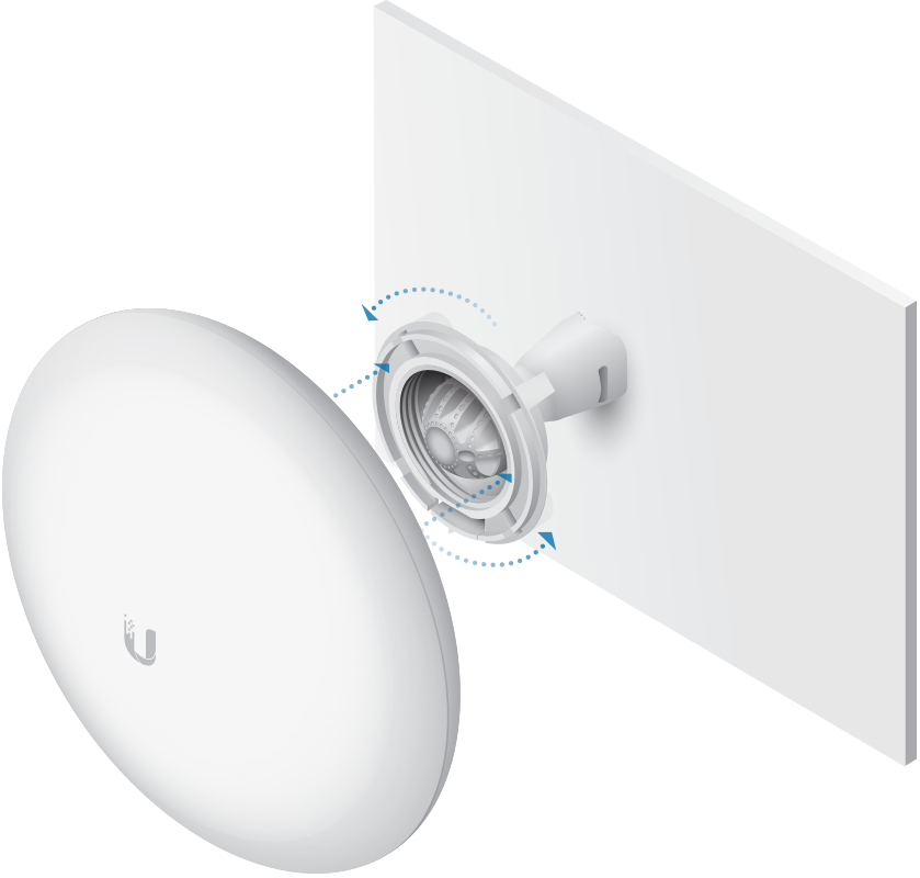
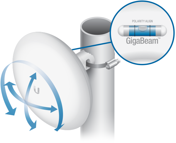
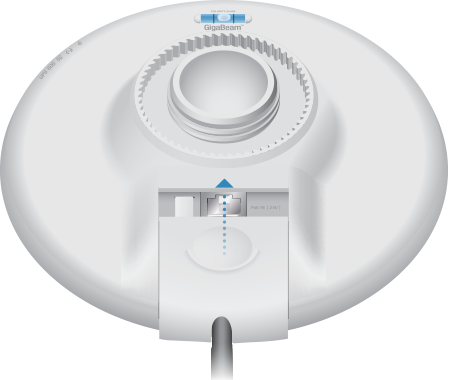
Aiming
Visually aim the GigaBeam radios at each other.
Connecting Power
| WARNING: The switch port must comply with the power specifications listed in “Specifications”. |
|---|

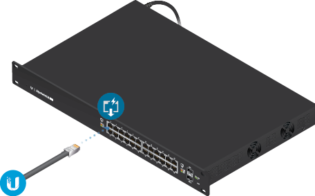
OR
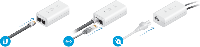
Optional
Configuration
The device is set to DHCP by default, so it will try to automatically obtain an IP address. If that fails, it will use the default fallback IP address, 192.168.1.20. Proceed to the appropriate section, DHCP or “Fallback IP Address”:
DHCP
Use one of the following methods:
- Set up the DHCP server to provide a specific IP address to the device based on its MAC address (on the label).
- Let the device obtain an IP address and then check the DHCP server to see which IP address was assigned.
- Connect a computer to your network and configure the Ethernet adapter on your computer with a static IP address on the 192.168.1.x subnet.
- Launch your web browser. In the address field, type: https://192.168.1.20
Then press enter (PC) or return (Mac).
- Select your Country and Language. You must agree to the Terms of Use to use the product. Click Continue.
- Enter a Username and Password, confirm the Password, and click Save.
- Click the
 icon.
icon. - Configure the following settings:
- For one device, enable Access Point mode. For the other device (the Station), keep Access Point disabled.
- Enter a name in the SSID field. This must be the same on both the AP and the Station.
- In the WPA2 Preshared Key field, enter a combination of alphanumeric characters (0-9, A-Z, or a-z).
Note: The key is an alphanumeric password between 8 and 63 characters long.
- Click Save Changes.
- Configure each device (AP and Station) with a unique IP address:
- Click the
 icon.
icon. - Review the Network settings to ensure that each device has a unique IP address. Each can get its IP address via DHCP, or use a static IP address.
- DHCP By default DHCP client is enabled; if there is a DHCP server on your network, the device will receive its address via DHCP.
- Static Select this option to disable the DHCP client and enter a static IP address.
Note: If DHCP client fails, the device will use the fallback IP address: 192.168.1.20
- Click Save Changes.
- Click the

Fallback IP Address
- Ensure that your computer (or other host machine) is connected to the same LAN as the GigaBeam.
- Configure the Ethernet adapter on your host system with a static IP address on the 192.168.1.x subnet.
- Launch your web browser. Type https://192.168.1.20 in the address field, and press enter (PC) or return (Mac).
- Select your Country and Language. You must agree to the Terms of Use to use the product. Click Continue.
- Enter a Username and Password, confirm the Password, and click Save.
- Click the icon.
- Configure the following settings:
- For one device, enable Access Point mode. For the other device (the Station), keep Access Point disabled.
- Enter a name in the SSID field. This must be the same on both the AP and the Station.
- In the WPA2 Preshared Key field, enter a combination of alphanumeric characters (0-9, A-Z, or a-z).
Note: The key is an alphanumeric password between 8 and 63 characters long.
- Click Save Changes.
- Configure each device (AP and Station) with a unique IP address:
- Click the icon.
- Review the Network settings to ensure that each device has a unique IP address. Each can get its IP address via DHCP, or use a static IP address.
- DHCP By default DHCP client is enabled; if there is a DHCP server on your network, the device will receive its address via DHCP.
- Static Select this option to disable the DHCP client and enter a static IP address.
Note: If DHCP client fails, the device will use the fallback IP address: 192.168.1.20
- Click Save Changes.
- Click the
Repeat the instructions in the “Configuration” section on the other GigaBeam.
UISP Management
You can manage your device using UISP, which lets you configure, monitor, upgrade, and back up your devices using a single application. Get started at uisp.ui.com
Installer Compliance Responsibility
Devices must be professionally installed and it is the professional installer’s responsibility to make sure the device is operated within local country regulatory requirements.
The 5GHz Output Power field is provided to the professional installer to assist in meeting regulatory requirements.
Specifications
|
GBE |
|
|
Dimensions |
140 x 140 x 44 mm (5.51 x 5.51 x 1.73) |
|---|---|
|
Weight |
376 g (13.3 oz) |
|
Enclosure |
UV-Resistant Polycarbonate |
|
Gain |
|
| 5 GHz | 10 dBi |
| 60 GHz | 17.2 dBi |
|
Networking Interface |
10/100/1000 Ethernet Port Wi-Fi for Management |
|
Max. Power Consumption |
11W |
|
Power Method |
Passive PoE (Pairs 4, 5+; 7, 8-) |
|
Power Supply |
24V, 0.5A Gigabit PoE Adapter (Included) |
|
Mounting |
Pole-Mount (Kit Included) Wall-Mount (Not Included) |
|
ESD/EMP Protection |
± 24kV Contact/Air |
|
Operating Temperature |
-40 to 60° C (-40 to 140° F) |
|
Operating Humidity |
5 to 95% Noncondensing |
|
Certifications |
CE, FCC, IC |
|
Radio |
|
|
Max. Conducted TX Power |
|
|---|---|
| 5/60 GHz Combined | 25 dBm |
|
Channel Bandwidth |
|
| 60 GHz | 2160 MHz |
| 5 GHz | 20/40/80 MHz |
|
Operating Frequency (GHz) |
||
|
Worldwide |
5.180 - 5.875 |
|
|---|---|---|
|
US/CA |
U-NII-1 |
5.180 - 5.250 |
U-NII-2A | 5.250 - 5.350 | |
U-NII-2C | 5.470 - 5.725 | |
U-NII-3 | 5.725 - 5.850 | |
|
57 - 66 |
||
|
Management Radio (MHz) |
|
|
Worldwide |
2412 - 2472 |
|---|---|
|
US/CA |
2412 - 2462 |