Package Contents
 |
|---|
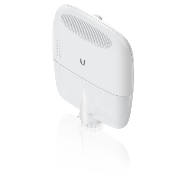
| EdgePoint Router |
 |
|---|
| Wall-Mount Bracket |
 |
|---|
| Metal Straps (Qty. 2) |
 |
|---|
| Cable Sleeve |
 |
|---|
| Cable Ties (Qty. 20) |
 |
|---|
| S2 Hex Wrench |
 |
|---|
| Wall-Mount Screws (Qty. 4) |
 |
|---|
| Wall-Mount Anchors (Qty. 4) |
 |
|---|
| Phillips Bolts (Qty. 2) |
 |
|---|
| Gigabit PoE (54V, 1.5A) with Mounting Bracket |
 |
|---|
| Power Cord |
 |
|---|
| PoE Screws (Qty. 2) |
 |
|---|
| PoE Anchors (Qty. 2) |
Installation Requirements
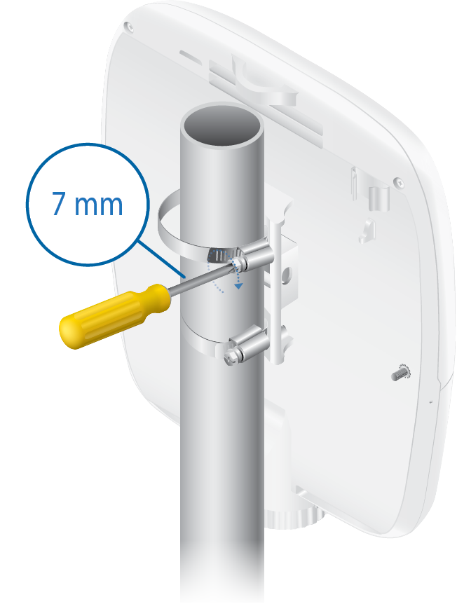
- 7 mm socket wrench
- S2 hex wrench
- Ground wire – min. 10 AWG (5 mm2) and max. length: 1 m. As a safety precaution, ground the EdgePoint to a grounded mast, pole, tower, or grounding bar.
- Shielded Category 5 (or above) cabling should be used for all wired Ethernet connections and should be grounded through the AC ground of the PoE.
We recommend that you protect your networks from harmful outdoor environments and destructive ESD events with industrial-grade, shielded Ethernet cable from Ubiquiti. For more details, visit: ui.com/toughcable
Power Options
Either the VDC or PoE input type is used at any one time. If both are connected, only the input type with the highest voltage will be used; the other can be used as a backup.
Both PoE inputs can be used at the same time. If there is a voltage difference, the higher-voltage source will be used first. The voltage from the initial source will drop as the load increases. When the voltage drops to the same level as the lower-voltage source, then the lower-voltage source will also start providing power.
Power Input Options
- 54VDC, 6A
- 54V, 1.5A on eth0 (PoE In)
- 54V, 1.5A on PoE In
Power Output Options
- EdgePoint (required)
- Passive 54/24V, 4-Pair PoE on eth1-eth2
- Passive 24V, 2-Pair PoE on
eth3-eth7
The number of devices that can be powered depends on the power consumption of the specific devices and the power input option. Example: If you provide 54VDC, 1.5A, then you have 81W of power. If the EdgePoint uses 40W (Max. Power Consumption), then you have 41W available for passive PoE output. Check product specifications for the power consumption values to use in your calculations.
Hardware Overview
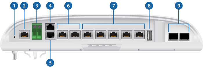
 Reset Button |
||
|---|---|---|
Click here to learn how to reset the EdgePoint to factory defaults. |
||
 Console Port |
||
RJ45 serial console port for Command Line Interface (CLI) management.
|
||
 DC Input |
||
Terminal block connector uses auto-polarity detection and accepts +42 to +56VDC, 6A input (including the Ubiquiti EdgePower™, model EP-54V-150W) to power the EdgePoint and passive PoE output. -48V is NOT supported. |
||

PoE In Port |
||
RJ45 port accepts 54V, 1.5A PoE input from a secondary PoE adapter (not included) to power the EdgePoint and passive PoE output. |
||
 PoE In / eth0 Port |
||
RJ45 port supports a 10/100/1000 Ethernet connection and accepts data and 54V, 1.5A PoE input from the included Gigabit PoE Adapter to power the EdgePoint and passive PoE output. |
||
 eth1 - eth2 Ports (54/24V PoE Out) |
||
RJ45 ports support 10/100/1000 Ethernet connections and passive 54/24V, 4-pair PoE output for airFiber® devices. |
||
 eth3 - eth7 Ports (24V PoE Out) |
||
RJ45 ports support 10/100/1000 Ethernet connections and passive 24V, 2-pair PoE output for airMAX® devices. RJ45 port eth6 and SFP 1 port are combination ports; eth6 is active only if the SFP 1 port is empty. RJ45 port eth7 and SFP 2 port are combination ports; eth7 is active only if the SFP 2 port is empty. |
||
 USB Port |
||
Reserved for future use. |
||
 SFP 1 - 2 Ports |
||
SFP ports are hot-swappable and support 100 Mbps or Gigabit fiber SFP modules. If an SFP module is plugged into the SFP 1 port, then the SFP port is active, and the RJ45 port eth6 is deactivated. If an SFP module is plugged into the SFP 2 port, then the SFP port is active, and the RJ45 port eth7 is deactivated.
|

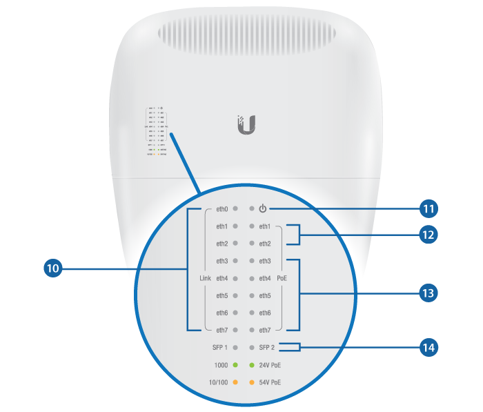

Speed/Link/Activity LED (eth0 - eth7 Ports) |
|
|---|---|
Off |
No Link |
Amber |
10/100 Mbps Link |
Green |
1000 Mbps (1 Gbps) Link |

Power LED |
|
Green |
EdgePoint Powered On |

PoE Output LED (eth1 - eth2 Ports) |
|
Off |
No PoE |
Amber |
54V, 4-Pair Passive |
Green |
24V, 4-Pair Passive |

PoE Output LED (eth3 - eth7 Ports) |
|
Off |
No PoE |
Green |
24V, 2-Pair Passive |

Speed/Link/Activity LED (SFP 1 - 2 Ports) |
|
Off |
No Link |
Amber |
100 Mbps Link |
Green |
1000 Mbps (1 Gbps) Link |

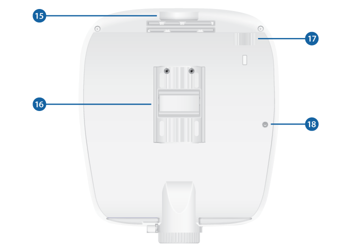
Lanyard Loop |
|
Used for temporary support during installation. |
|

Pole-Mount Bracket |
|
Used for pole-mounting or in combination with the included Wall-Mount Bracket for wall-mounting. |
|

PicoStation®M2HP Slot |
|
Used for mounting an optional PicoStationM2HP (not included) to the back of the EdgePoint. (You can use the PicoStationM2HP for wireless management of the EdgePoint.) |
|

Ground Bonding Point |
|
Used to secure a ground wire (not included). |
|
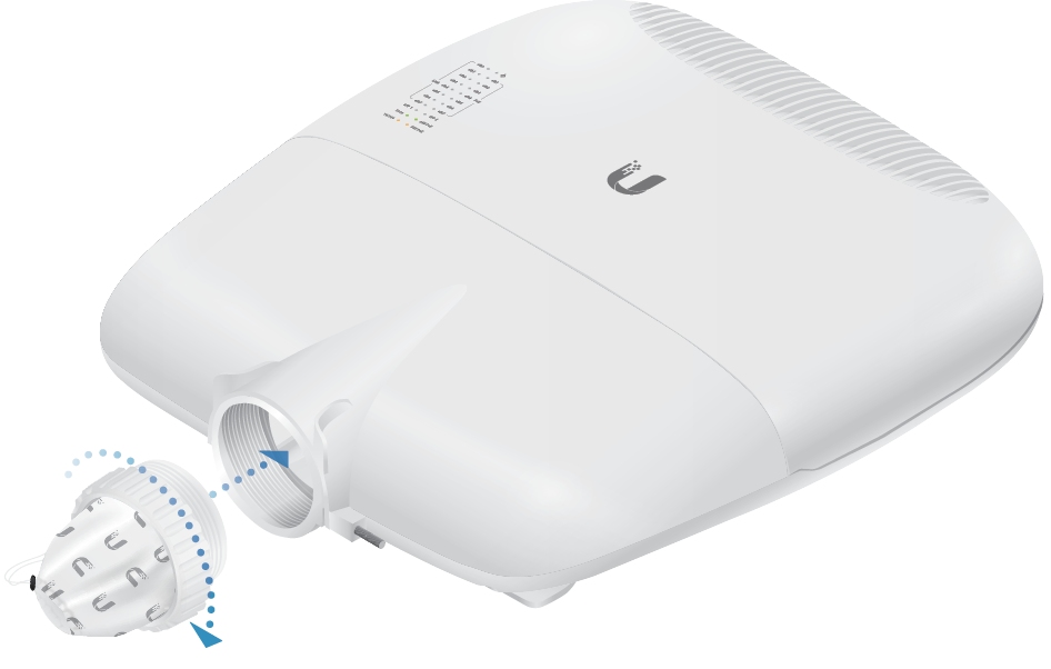
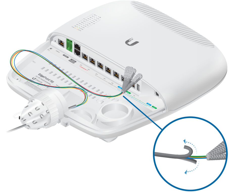
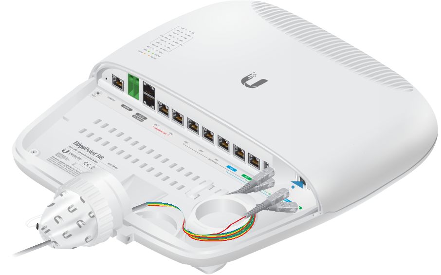
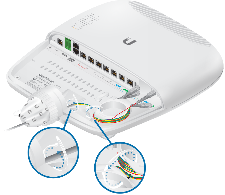
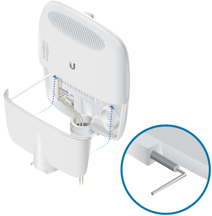
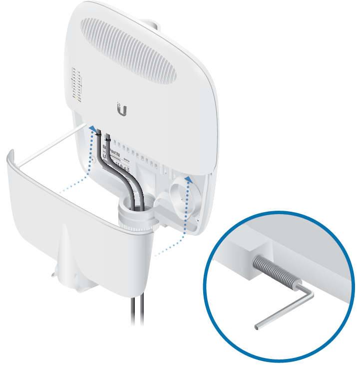
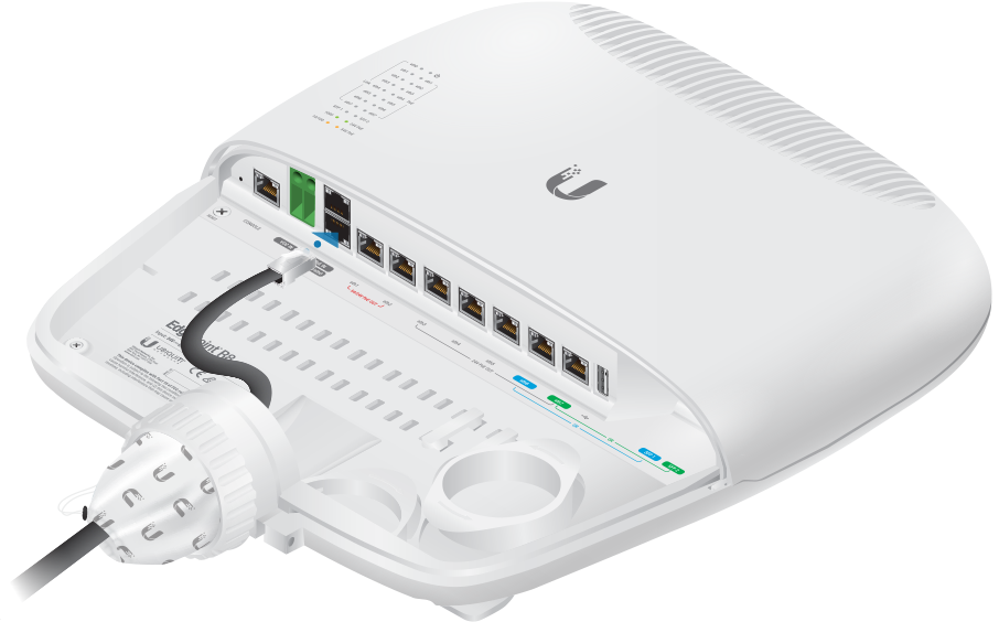
Attaching the Cable Sleeve
|
|
Note: You have two options for using a 2.0-inch NPT (National Pipe Thread) male conduit (not included):
|
|---|

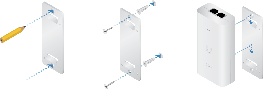
Hardware Installation
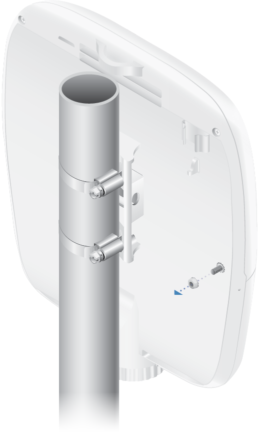
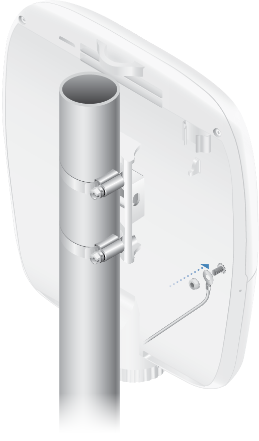
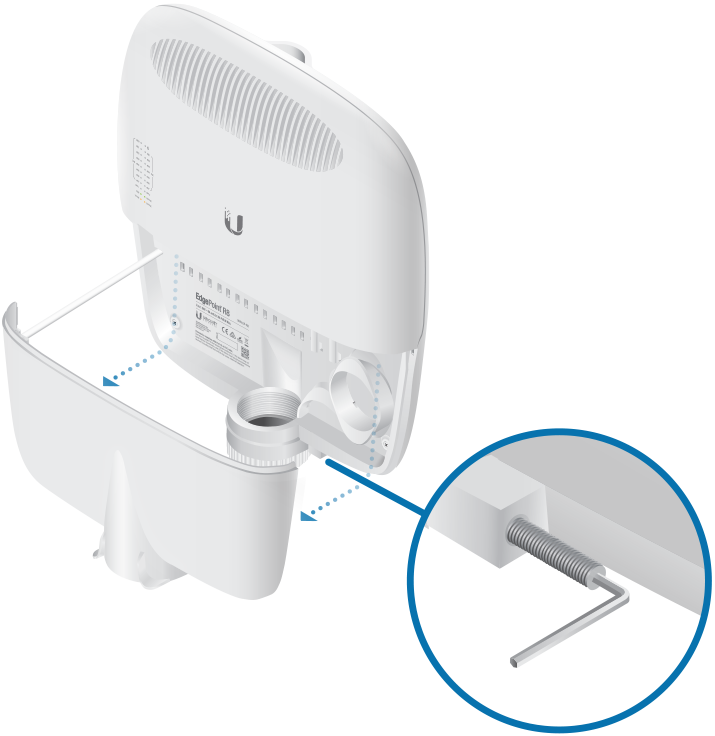
Mount the EdgePoint on a pole or to a wall:
Pole-Mounting
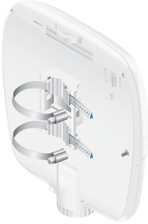
- Proceed to "Grounding the EdgePoint".
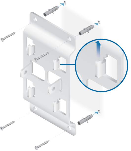
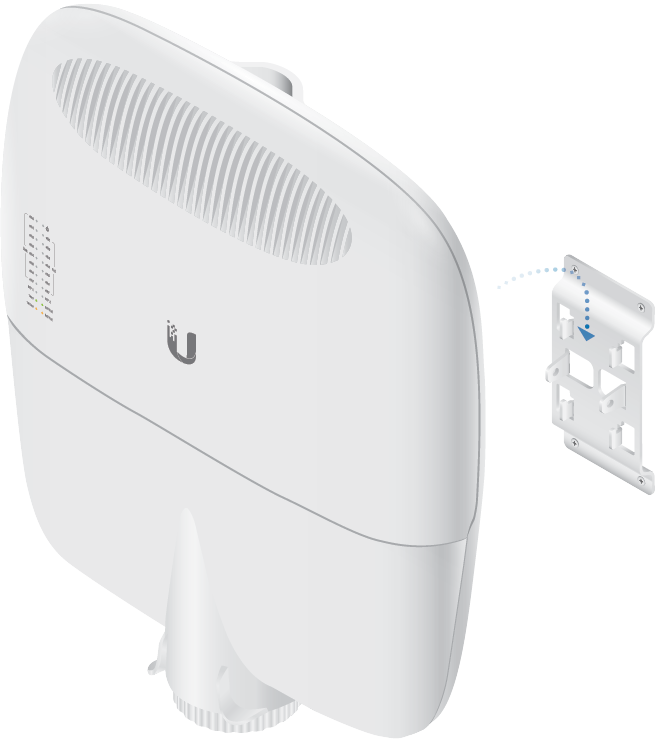
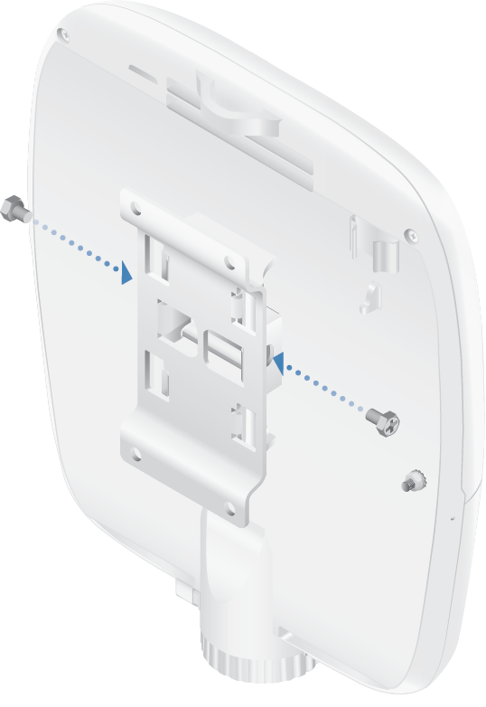
Wall-Mounting
|
|
Note: The Wall-Mount Bracket must be anchored directly to a stud or other structurally stable surface. |
|---|
Grounding the EdgePoint
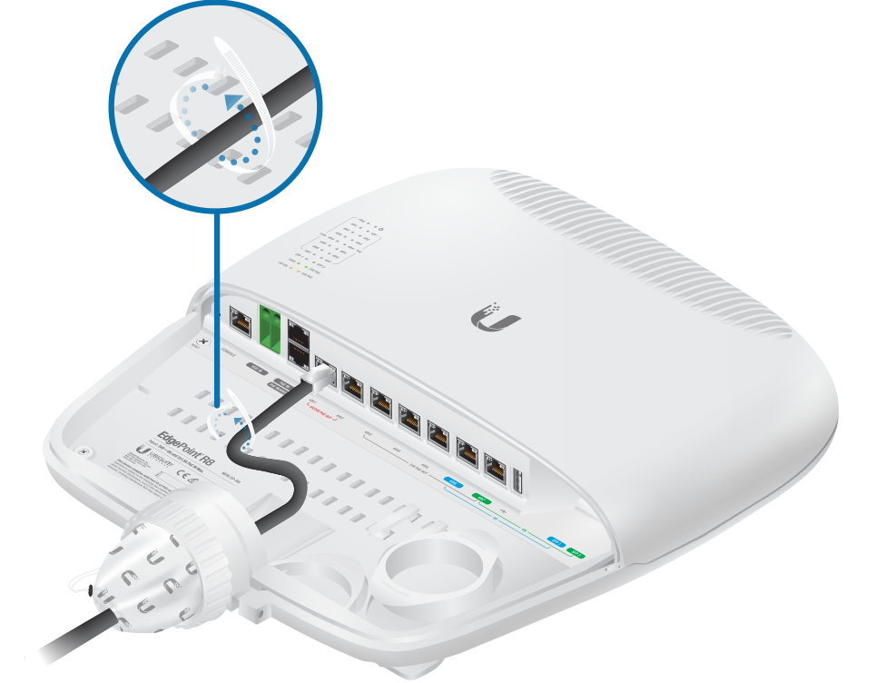
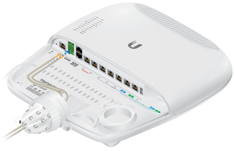
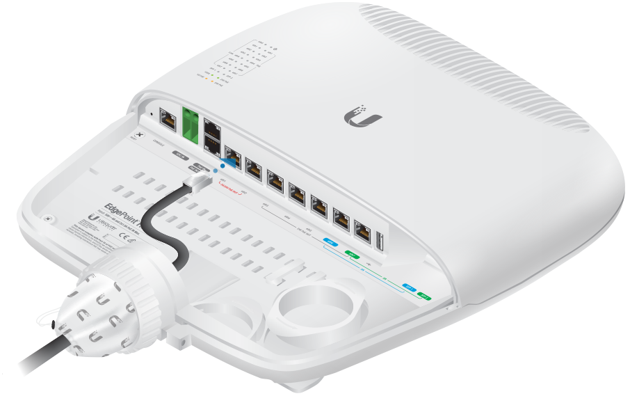
Connecting Ethernet
| Note: PoE is disabled by default. |
|---|
![]()
Connecting SFP
For information about compatible fiber SFP modules, visit: ubnt.link/SFP_DAC_Compatibility
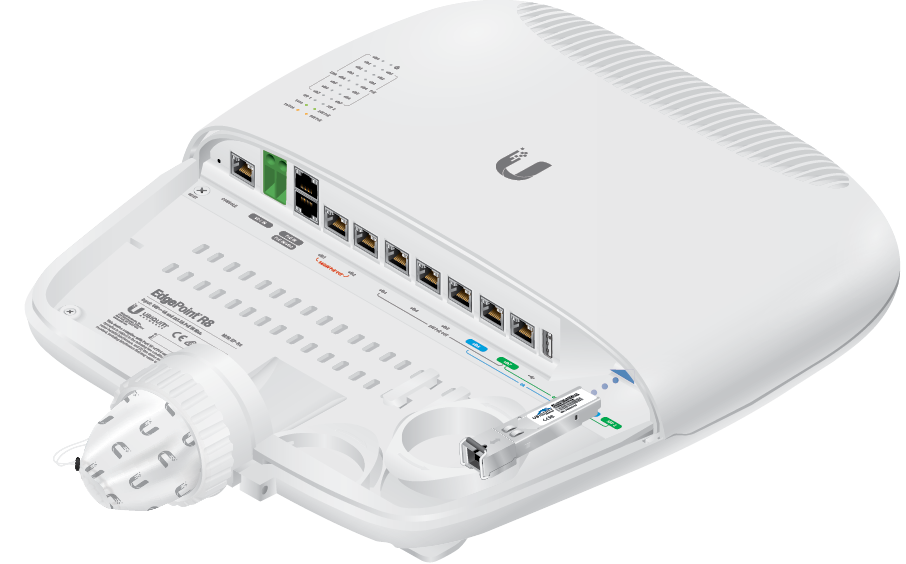
| Note: The corresponding RJ45 port will be deactivated. |
|---|
Connecting Power
Proceed to the appropriate section:
|
|
WARNING: -48V is NOT supported. |
|---|

Connecting to the VDC Input
Connecting Power Using PoE
The following instructions show the PoE In / eth0 port; however, you can use the PoE In port above eth0 instead.
Optional
Accessing the EdgeOS Configuration Interface
The EdgeOS® configuration interface can be accessed via DHCP or static IP address assignment. By default, eth1 is set up as a DHCP client, while eth0 is assigned a static IP address of 192.168.1.1. To configure the EdgePoint, proceed to the appropriate section: DHCP or "Static IP Address".
DHCP
Use one of the following methods:
- Set up the DHCP server to provide a specific IP address to the EdgePoint based on its MAC address (on the label).
- Let the EdgePoint obtain an IP address and then check the DHCP server to see which IP address was assigned.
- Connect an Ethernet cable from eth1 on the EdgePoint to a LAN segment that has an existing DHCP server.
- Launch your web browser. Enter the appropriate IP address in the address field. Press enter (PC) or return (Mac).
- Enter ubnt in the Username and Password fields. Read the Ubiquiti License Agreement, and check the box next to I agree to the terms of this License Agreement to accept it. Click Login.
- Connect an Ethernet cable from eth1 on the EdgePoint to a LAN segment that has an existing DHCP server.
The EdgeOS Configuration Interface will appear, allowing you to customize your settings as needed. For more information, refer to the EdgeOS User Guide, which is available at ui.com/download/edgemax
For more information on PoE configuration, refer to "Configuring PoE Settings".
Static IP Address
- Connect an Ethernet cable from the Ethernet port on your computer to the port labeled eth0 on the EdgePoint. (If you are using PoE, connect your computer to the EdgePoint via a PoE switch, or to the adapter’s LAN port.)
- Configure the Ethernet adapter on your host system with a static IP address on the 192.168.1.x subnet.
- Launch your web browser. Type https://192.168.1.1 in the address field, and press enter (PC) or return (Mac).
- Enter ubnt in the Username and Password fields. Read the Ubiquiti License Agreement, and check the box next to I agree to the terms of this License Agreement to accept it. Click Login.
The EdgeOS Configuration Interface will appear, allowing you to customize your settings as needed. For more information, refer to the EdgeOS User Guide, which is available at ui.com/download/edgemax
For more information on PoE configuration, refer to "Configuring PoE Settings".
UISP Management
You can manage your device using UISP, which lets you configure, monitor, upgrade, and back up your devices using a single application. Get started at uisp.ui.com
Configuring PoE Settings
|
|
WARNING: Before activating 54V or 24V passive PoE, ensure that the connected device supports PoE and the supplied voltage. |
|---|

- Go to Actions > PoE for the interface you want to configure.
- Configure the PoE setting:
- For eth1-eth2, select Off, 24V-4pair, or 54V-4pair.
- For eth3-eth7, select Off or 24V .
Then click Save.
| WARNING: Do NOT connect 4-pair PoE devices, such as airFiber devices, to ports eth3-eth7. They support 2-pair PoE only. |
|---|
|
|
Note: If the PoE screen states that PoE is not supported, then there is insufficient power. You will need to increase the power input to the EdgePoint. |
|---|
For more information, refer to the EdgeOS User Guide, which is available at ui.com/download/edgemax
Specifications
|
EP-R8 |
|
|
Dimensions |
326.6 x 382.7 x 88.8 mm (12.86 x 15.07 x 3.50") |
|---|---|
| With Wall-Mount | 326.6 x 382.7 x 105.5 mm (12.86 x 15.07 x 4.15") |
|
Weight |
3.4 kg (7.50 lb) |
| With Wall-Mount | 3.8 kg (8.38 lb) |
|
Max. Power Consumption |
40W (Excludes PoE Output) |
|
Power Input |
(1) DC Terminal Block or (2) RJ45 (PoE In and eth0) (Self-Correcting Polarity Protection on DC Terminal Block Only, |
|
Power Supply |
Min. 54V / 0.8A (Excludes PoE Output Power) |
|
VDC Input |
54V / 6A |
|
Passive PoE Input |
(2) 54V / 1.5A, 4-Pair (+1, 2, 4, 5; -3, 6, 7, 8) Passive PoE, eth0 and PoE In (PoE In: DC Only) |
|
Passive PoE Output |
(2) 54V or 24V / 1.4A, 4-Pair (+1, 2, 4, 5; -3, 6, 7, 8) Passive PoE, eth1 to eth2 (5) 24V / 0.7A, 2-Pair (+4, 5; -7, 8) Passive PoE, eth3 to eth7 |
|
Power Monitoring |
(1) DC Terminal Block, Input Power (2) RJ45, PoE In and eth0, Input Power |
|
Supported Voltage Range |
+42 to +56VDC |
|
Button |
Reset |
|
LEDs |
|
| System | Power |
| eth0 | Speed/Link/Activity |
| eth1 to eth7 | Speed/Link/Activity, PoE |
| SFP | Speed/Link/Activity |
|
Ports |
|
| Serial Console Port | (1) RJ45 Serial Port |
| PoE In Port | (1) RJ45 Port |
| Data Ports | (6) 10/100/1000 RJ45 Ports (2) 10/100/1000 RJ45/SFP Combination Ports |
|
Processor |
Dual-Core 600 MHz, MIPS64 with Hardware Acceleration for Packet Processing |
|
System Memory |
2 GB DDR3-1600 RAM |
|
Code Storage |
4 GB |
|
Certifications |
CE, FCC, IC |
|
Pole/Wall Mount |
Yes |
|
Operating Temperature |
-40 to 65° C (-40 to 149° F) |
|
Operating Humidity |
10 - 90% Noncondensing |