Package Contents
 |
|---|
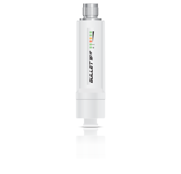
| Bullet M2 |
 |
|---|
| Compression Seal |
Installation Requirements
- Shielded Category 5 (or above) cabling with drain wire should be used for all outdoor wired Ethernet connections and should be grounded through the AC ground of the PoE.
We recommend that you protect your networks from harmful outdoor environments and destructive ESD events with industrial-grade, shielded Ethernet cable from Ubiquiti.. For more details, visit ui.com/toughcable
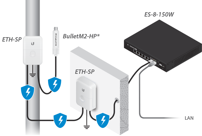
- Surge protection should be used for all outdoor installations. We recommend that you use two Ethernet Surge Protectors, model ETH-SP, one near the B-DB-AC and the other at the entry point to the building. The ETH-SP will absorb power surges and safely discharge them into the ground.
* Shown without antenna.
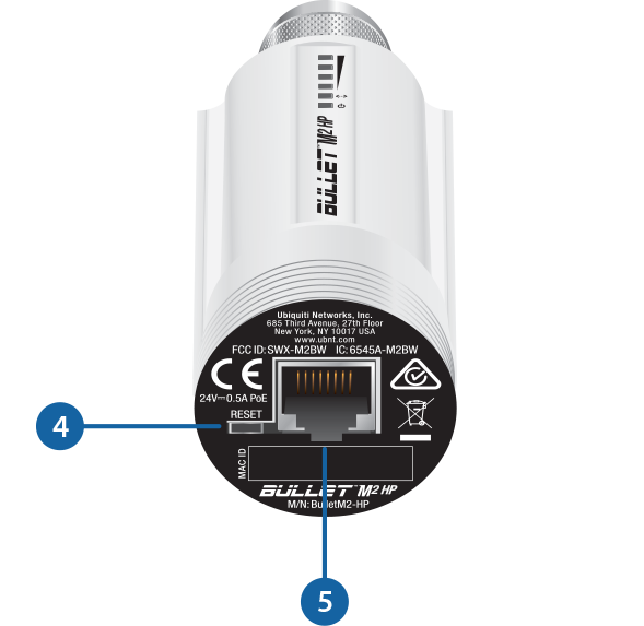
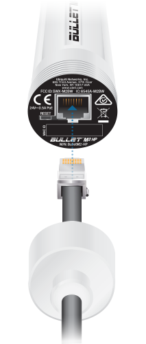
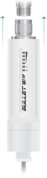
Hardware Overview
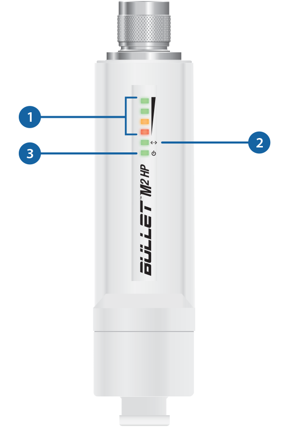
 Signal LEDs |
|---|
In airOS®, you can modify the threshold values for the wireless signal strength LEDs on the Advanced tab under Signal LED Thresholds. The default values are shown below:
|

Ethernet LED |
The Ethernet LED will light steady green when an active Ethernet connection is made and flash when there is activity. |

Power LED |
The Power LED will light green when the device is connected to a power source. |

Reset Button |
To reset to factory defaults, press and hold the Reset button for more than 10 seconds while the device is powered on. |

Ethernet Port |
This 10/100 Ethernet port is used to connect the power and should be connected to the LAN and DHCP server. |

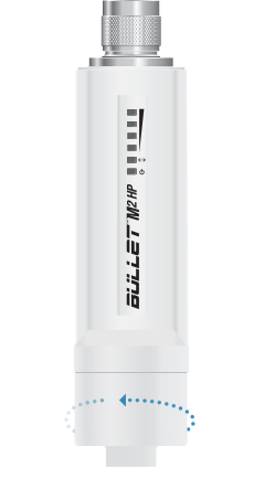
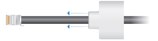
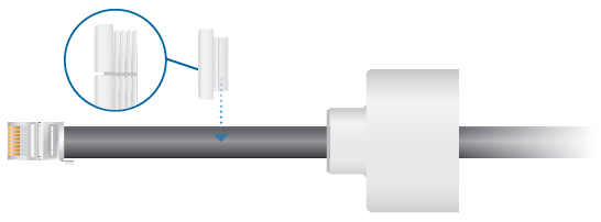
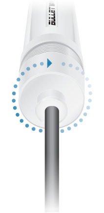
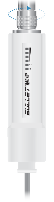
Hardware Installation

|
|
Accessing airOS
Verify connectivity in the airOS® Configuration Interface.
- Make sure that your host machine is connected via Ethernet to the device.
- Configure the Ethernet adapter on your host system with a static IP address on the 192.168.1.x subnet.
- Launch your web browser and type https://192.168.1.20 in the address field. Press enter (PC) or return (Mac).

- Enter ubnt in the Username and Password fields. Select your Country and Language. You must agree to the Terms of Use to use the product. Click Login.
The airOS Configuration Interface will appear, allowing you to customize your settings as needed. For additional details on the airOS Configuration Interface, refer to the User Guide available at: ui.com/download/airmax
You can also manage your device using the Ubiquiti Network Management System. Setup using the UISP™ app requires the U-Installer, sold separately.
Installer Compliance Responsibility
Devices must be professionally installed and it is the professional installer’s responsibility to make sure the device is operated within local country regulatory requirements.
Antena
Select your antenna from the list. Ensure Calculate EIRP Limit is enabled; transmit output power is automatically adjusted to comply with the regulations of the applicable country. For a Custom antenna, Antenna Gain is entered manually. Note the requirements and antenna types listed below.
Cable Loss (When applicable)
Enter the cable loss in dB. Output power is adjusted to compensate for loss between the radio and the antenna.
Certified Antenna Types
This radio transmitter FCC ID: FCC: SWX-M2BW / IC: 6545A-M2BW has been approved by FCC / ISED Canada to operate with the antenna types listed below with the maximum permissible gain for each antenna type indicated. Antenna types not included in this list or having a gain greater than the maximum gain indicated for that type, are strictly prohibited for use with this device.
|
Antenna |
Frequency |
Gain |
|---|---|---|
|
Omni |
2.4 GHz |
13 dBi |
|
Sector |
2.4 GHz |
17 dBi |
|
Dish |
2.4 GHz |
24 dBi |
Specifications
|
BulletM2-HP |
|
|
Dimensions |
163.65 x 38.75 x 38.75 mm |
|---|---|
|
Weight |
130 g (4.59 oz) |
|
Enclosure |
Polycarbonate |
|
Networking Interface |
10/100 Mbps |
|
Antenna Connector |
N-Type Connector |
|
LEDs |
Power, Ethernet, |
|
Max. Power Consumption |
7W |
|
Output Power |
25 dBm |
|
Power Supply |
AC to 24VDC, 0.5A Gigabit PoE Adapter |
|
Power Method |
24V Passive PoE |
|
ESD/EMP Protection |
± 24 kV Contact/Air |
Operating Temperature |
-40 to 70° C (-40 to 158° F) |
|
Operating Humidity |
5 to 95% Condensing |
|
Shock and Vibration |
ETSI300-019-1.4 |
|
Certifications |
CE, FCC, IC |
|
Operating Frequency (MHz) |
|
|
US/CA |
2412 - 2462 |
|---|---|
|
Worldwide |
2412 - 2472 |