Package Contents
 |
|---|
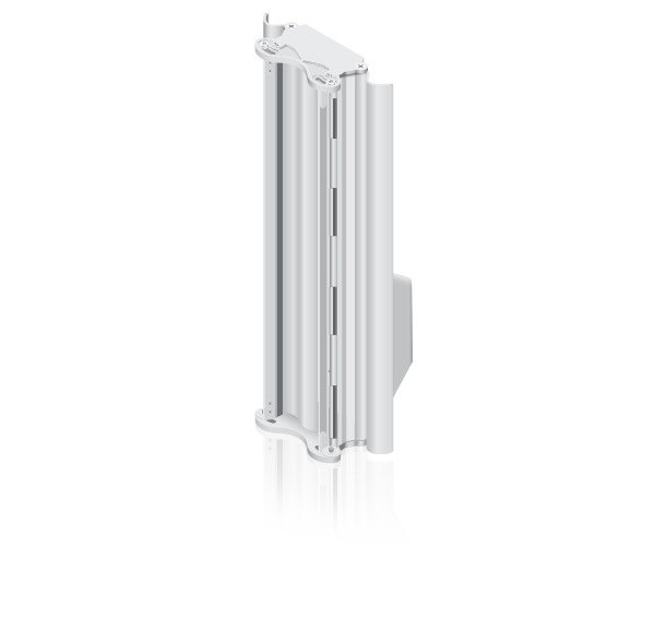
| Antenna |
 |
|---|
| Protective Shroud |
 |
|---|
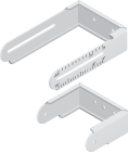
| U-Brackets (Qty. 2) |
 |
|---|
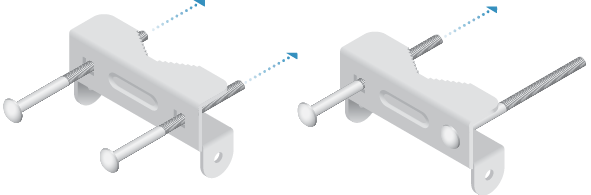
| Pole Brackets (Qty. 2) |
 |
|---|
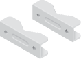
| Pole Clamps (Qty. 2) |
 |
|---|
| Carriage Bolts (Qty. 4) |
 |
|---|
| Serrated Flange Bolts (Qty. 4) |
 |
|---|
| Serrated Flange Nuts (Qty. 8) |
 |
|---|
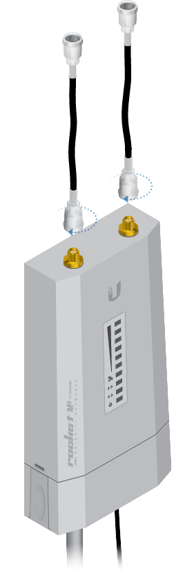
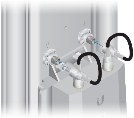
| RF Cables (Qty. 2) |
Installation Requirements
- Rocket®M5, RocketM5 GPS, or RocketM5 Titanium (sold separately)
- 3 mm hex key driver
- 12 mm and 13 mm wrenches
- Shielded Category 5 (or above) cabling should be used for all wired Ethernet connections and should be grounded through the AC ground of the PoE.
We recommend that you protect your networks from harmful outdoor environments and destructive ESD events with industrial-grade, shielded Ethernet cable from Ubiquiti. For more details, visit ui.com/toughcable
Before You Begin
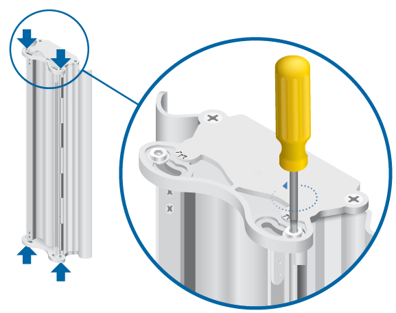
- Loosen the four hex head screws enough to move the Beamwidth Deflectors, but do not remove the screws.
- Carefully move the Beamwidth Deflectors to the desired angle, as indicated by the screw slots.
- Tighten the four hex head screws.

120° Beamwidth

90° Beamwidth

60° Beamwidth
| Important: Both deflectors must be set to the same angle. |
|---|


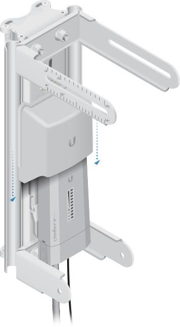
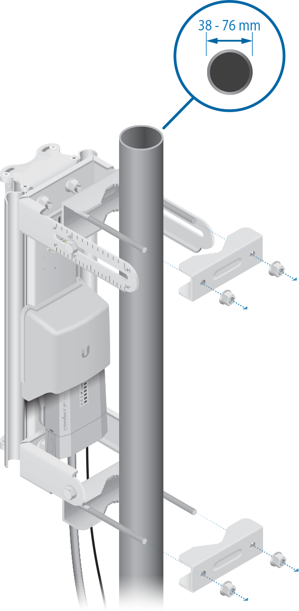
Hardware Installation
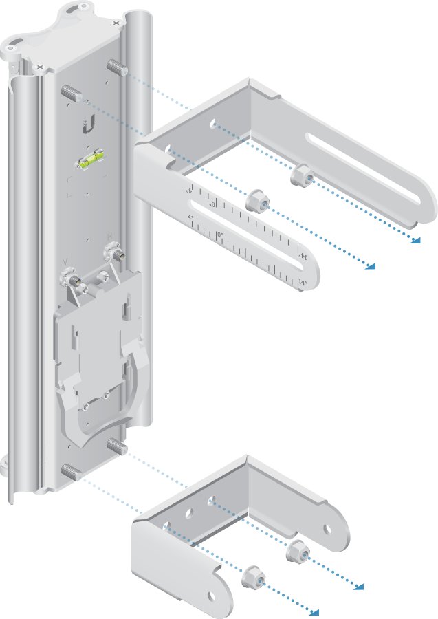
|
| Note: Orient both U-Brackets as shown. |
|---|

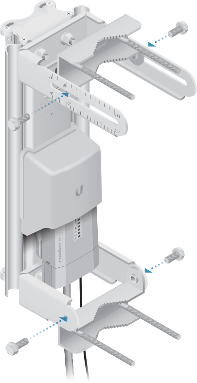
|
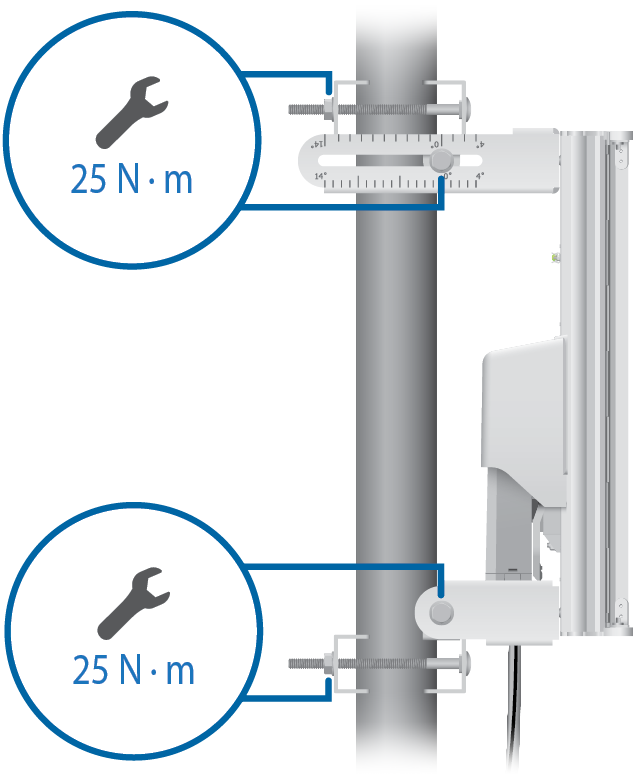
| Note: Hand-tighten the bolts. |
|---|
|
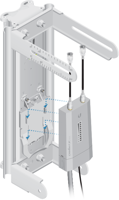
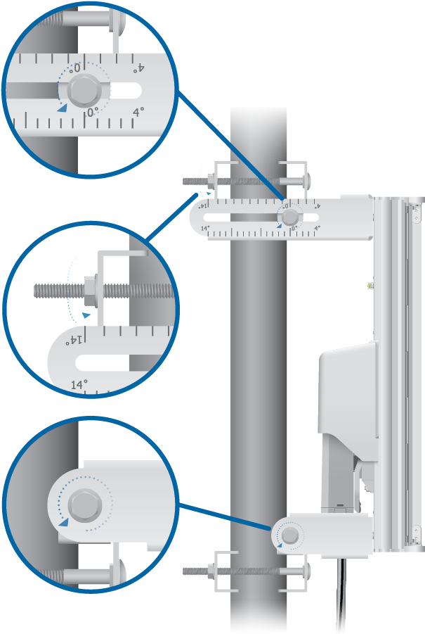
| Note: The antenna has an electrical downtilt of 3°. |
|---|
|
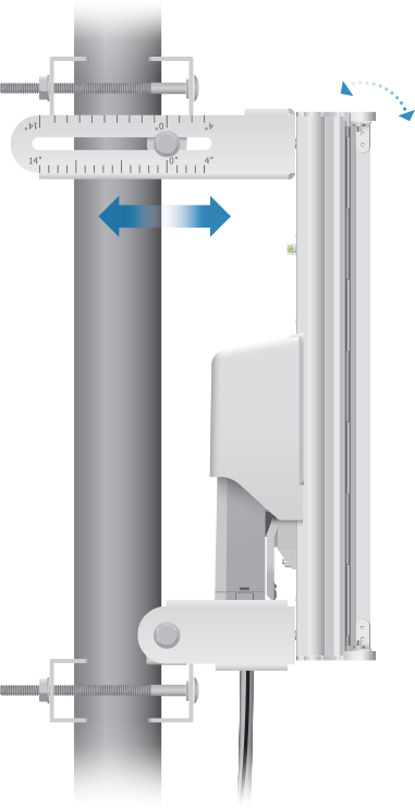
| Note: The brackets may slide along the pole, depending on the angle of the elevation tilt. |
|---|
Specifications
|
AM-M-V5G-Ti |
|
|
Dimensions |
385 x 149 x 76 mm (15.16 x 5.87 x 2.99") |
|---|---|
|
Weight (with Brackets) |
3.25 kg (7.17 lb) |
|
Frequency Range |
5.45 - 5.85 GHz |
|
Beamwidth Angles |
60°/ 90°/ 120° |
|
Gain |
17 dBi @ 60° 16 dBi @ 90° 15 dBi @ 120° |
|
Electrical Downtilt |
3° |
|
Wind Survivability |
200 km/h (125 mph) |
|
Wind Loading |
102 N @ 200 km/h (23 lbf @ 125 mph) |
|
Polarization |
Dual Linear |
|
Cross-Pol Isolation |
25 dB Typical |
|
F/B Ratio |
35 dB Typical |
|
Max. VSWR |
1.7:1 |
|
RF Connectors |
2 RP-SMA Connectors (Weatherproof) |
|
Compatible Radios |
RocketM5 Titanium RocketM5 RocketM5 GPS |
|
Mounting |
Pole Mount (Kit Included) |
|
ETSI Specification |
EN 302 326 DN2 |
|
Certifications |
CE, FCC, IC |