Package Contents
 |
|---|
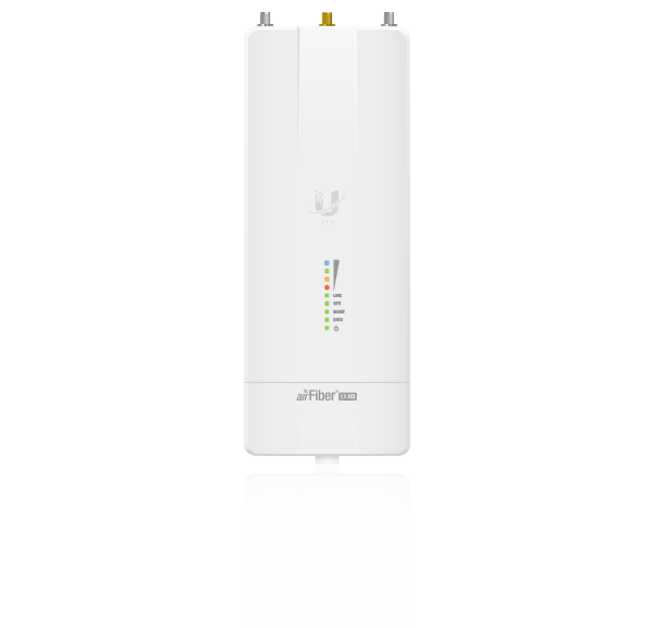
| airFiber AF-5XHD |
 |
|---|
| GPS Antenna Mount |
 |
|---|
| External GPS Antenna |
 |
|---|
| Metal Strap |
 |
|---|
| Zip Ties (Qty. 2) |
 |
|---|
| Universal Bracket |
 |
|---|
| IP67 Upgrade Kit (Vent and Gasket) |
 |
|---|
| Gigabit PoE (24V, 1A) with Mounting Bracket |
 |
|---|
| Power Cord |
Antenna Compatibility
The airFiber AF-5XHD radio is designed for use with the following airFiber X antenna models:
- AF-5G23-S45
- AF-5G30-S45
- AF-5G34-S45
The AF-5XHD can also operate with the following RocketDish™ antenna models:
- RD-5G30*
- RD-5G34*
* Requires Universal Bracket (included) or AF-5G-OMT-S45 Conversion Kit (not included).
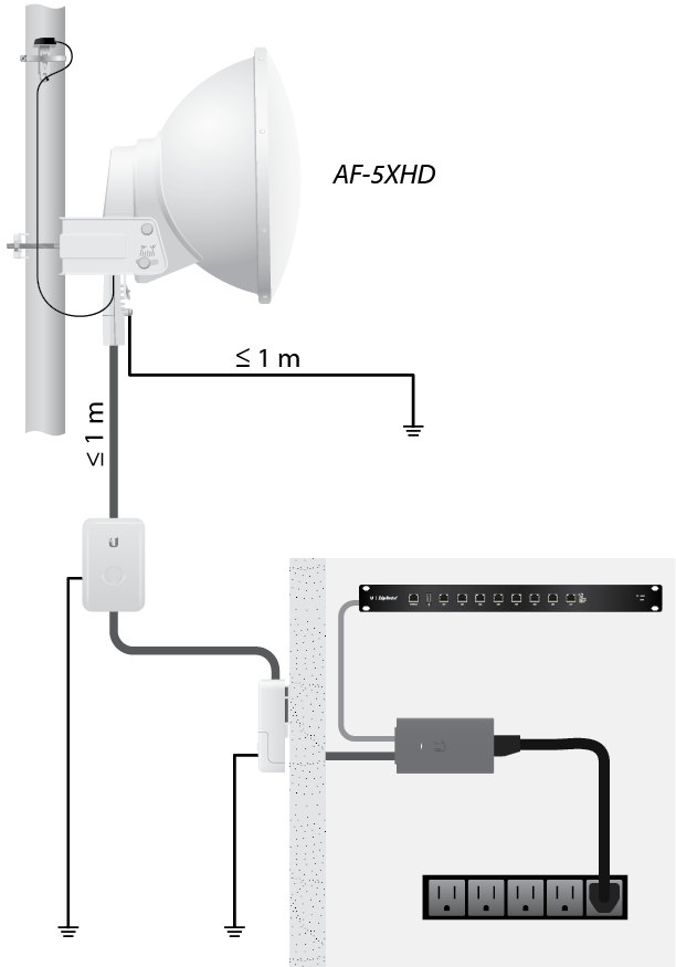
Installation Requirements
- Clear line of sight between airFiber radios
- Clear view of the sky for proper GPS operation
- Vertical mounting orientation
- Mounting point:
- At least 1 m below the highest point on the structure
- For tower installations, at least 3 m below the top of the tower
- Ground wires – min. 10 AWG (5 mm2) and max. length: 1 m. As a safety precaution, ground the airFiber radio to grounded masts, poles, towers, or grounding bars.
- (Recommended) 2 Outdoor Gigabit PoE surge protectors
- Outdoor, shielded Category 6 (or above) cabling and shielded RJ-45 connectors are required for all wired Ethernet connections.
| WARNING: Failure to properly ground your airFiber radio will void your warranty. |
|---|

| Note: For guidelines about grounding and lightning protection, follow your local electrical regulatory codes. |
|---|
Hardware Overview
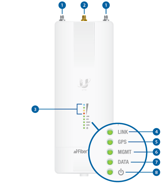

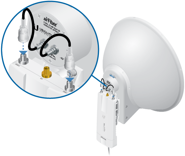
airFiber Antenna Connectors |
|||||||||||||||||||||||||||||||||||||||||||||
|---|---|---|---|---|---|---|---|---|---|---|---|---|---|---|---|---|---|---|---|---|---|---|---|---|---|---|---|---|---|---|---|---|---|---|---|---|---|---|---|---|---|---|---|---|---|
Used to attach RF antenna cables (not included). |
|||||||||||||||||||||||||||||||||||||||||||||

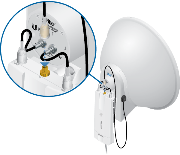
GPS Antenna Connector |
|||||||||||||||||||||||||||||||||||||||||||||
Used to attach the GPS Antenna. |
|||||||||||||||||||||||||||||||||||||||||||||

Signal LEDs |
|||||||||||||||||||||||||||||||||||||||||||||
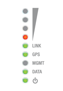
Bootup to airOS When powering on, the Power, GPS, Link, and Signal 1-4 LEDs light on. Once the CPU code takes over, the GPS, Link, and Signal 1-3 LEDs turn off. The Signal 4 LED remains on to indicate the boot sequence is underway. Initializing airFiber Software When the airFiber application begins to boot under airOS®, the Signal 4 LED goes from solidly on to a 2.5 Hz flash. This continues until the AF-5XHD is fully booted. Signal Level Once fully booted, the Signal 1-4 LEDs act as a bar graph showing how close the AF-5XHD is to ideal aiming. This is auto-scaled based on the link range, the antenna gains, and the configured TX power of the remote AF-5XHD. Each Signal LED has three possible states: On, Flashing, and Off. All Signal LEDs would be solidly on in an ideal link. If the link has a 1 dB loss, the Signal 4 LED will flash; a 2 dB loss and the Signal 4 LED will turn off. The full bar graph LED states are shown below.
|
|||||||||||||||||||||||||||||||||||||||||||||

Link LED |
|||||||||||||||||||||||||||||||||||||||||||||
Off |
RF Off |
||||||||||||||||||||||||||||||||||||||||||||
 |
Syncing |
||||||||||||||||||||||||||||||||||||||||||||
 |
Beaconing |
||||||||||||||||||||||||||||||||||||||||||||
 |
Registering |
||||||||||||||||||||||||||||||||||||||||||||
On |
Operational |
||||||||||||||||||||||||||||||||||||||||||||

GPS LED |
|||||||||||||||||||||||||||||||||||||||||||||
Off |
No GPS Synchronization |
||||||||||||||||||||||||||||||||||||||||||||
|
Non-Operational (Weak Signal) |
||||||||||||||||||||||||||||||||||||||||||||
On |
Operational (Strong Signal) |
||||||||||||||||||||||||||||||||||||||||||||

MGMT LED |
|||||||||||||||||||||||||||||||||||||||||||||
Off |
No Ethernet Link |
||||||||||||||||||||||||||||||||||||||||||||
On |
Ethernet Link Established |
||||||||||||||||||||||||||||||||||||||||||||
Random Flash |
Ethernet Activity |
||||||||||||||||||||||||||||||||||||||||||||

Data LED |
|||||||||||||||||||||||||||||||||||||||||||||
Off |
No Ethernet Link |
||||||||||||||||||||||||||||||||||||||||||||
On |
Ethernet Link Established |
||||||||||||||||||||||||||||||||||||||||||||
Random Flash |
Ethernet Activity |
||||||||||||||||||||||||||||||||||||||||||||

Power LED |
|||||||||||||||||||||||||||||||||||||||||||||
Off |
No Power |
||||||||||||||||||||||||||||||||||||||||||||
On |
Powered On |
||||||||||||||||||||||||||||||||||||||||||||
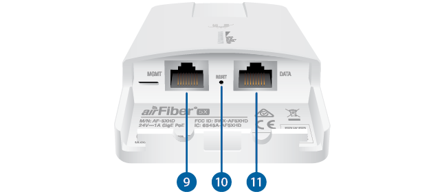
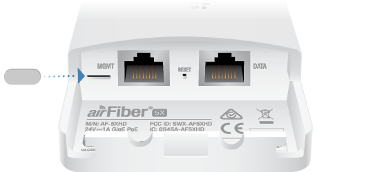
 Management Port |
|||||||||||||||||||||||||||||||||||||||||||||
10/100/1000 Mbps, secured Ethernet port for configuration. In-Band Management is enabled by default in the airFiber Configuration Interface. When In-Band Management is disabled, the MGMT port is the only port that can monitor, configure, and/or update firmware. This port can also be used to provide redundant PoE power. Default IP address: 192.168.2.20 |
|||||||||||||||||||||||||||||||||||||||||||||
 Reset Button |
|||||||||||||||||||||||||||||||||||||||||||||
To reset to factory defaults, press and hold the Reset button for more than 10 seconds while the device is powered on. |
|||||||||||||||||||||||||||||||||||||||||||||
 Data Port |
|||||||||||||||||||||||||||||||||||||||||||||
Gigabit PoE port for handling all user traffic and powering the device. Default IP address: 192.168.1.20 |
|||||||||||||||||||||||||||||||||||||||||||||


Installation Overview
We recommend that you configure your paired AF-5XHD radios before site installation. The overview below summarizes the installation procedure, and the subsequent sections provide detailed installation information.
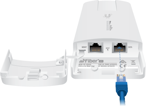
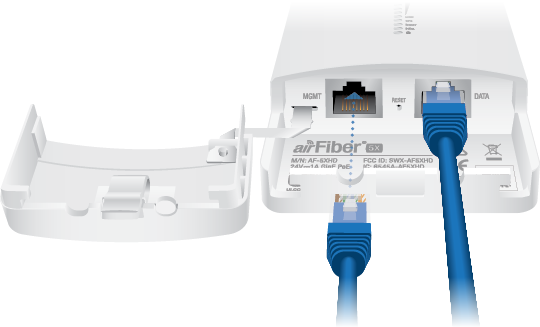
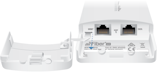
- Connect the airFiber PoE Adapter to the Data port, and connect your computer to the MGMT port.
- Configure the AF-5XHD.
- Recommended: Install the IP67 Upgrade Kit (included) to prevent intrusion by water, dust, and insects.
- Install a ground wire and mount the AF-5XHD on an airFiber X or RocketDish antenna.
- At the installation site, install the airFiber X or RocketDish antenna with the mounted AF-5XHD radio (see the antenna’s Quick Start Guide for installation instructions).
- Secure the ground wire and mount the GPS antenna.
- Establish and optimize the RF link.
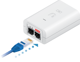
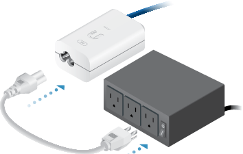
Connecting Power over Ethernet
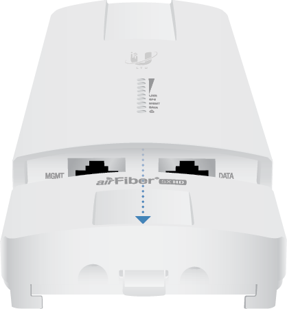
| WARNING: Use only the included adapter, model POE-24V-5X-HD. Failure to do so can damage the unit and void the product warranty. |
|---|
airFiber Configuration
The instructions in this section explain how to access the airFiber Configuration Interface and configure the following settings:
- Wireless Mode Configure one AF-5XHD as the Master and the other as the Slave.
- Frequency Setting The operating Frequency must be the same on both the Master and the Slave.
There are two methods for configuration:
- Ubiquiti® Network Management System (preferred method)
- airFiber Configuration Interface (browser-based interface)
Configuration Using UISP

![]()
![]()
- Launch the UISP app.
- Optional: Enable Bluetooth on your mobile device.
- On the Connections screen, select the AF-5XHD.
- Enter ubnt in the Username and Password fields. Select your Country and Language. You must agree to the Terms of Use to use the product.
- On the Summary screen, tap Configuration, and then tap Wireless.
- Configure these settings:
- On one AF-5XHD, enable Master Mode; on the other AF-5XHD, keep the default setting (Off) for Master Mode.
- Enter a name in the Link Name field. This should be the same on both the Master and the Slave.
- Select your Country.
- If needed, change the Channel Bandwidth, Frequency, Output Power (EIRP), Antenna Gain, and Max TX Modulation settings. The Channel Bandwidth and Frequency should be the same on both the Master and the Slave.
- In the Security Key field, enter a combination of alphanumeric characters (0-9, A-Z, or a-z).

Note: U.S. product versions are locked to the U.S. Country Code to ensure compliance with FCC regulations.
Note: The key is an alphanumeric password between 8 and 63 characters long.
- Click Save Changes.
- Configure each airFiber radio with a unique IP address for the Data port:
- Tap Configuration, and then tap Network.
- For both the Data LAN Network and Management Network options:
- DHCP Have your router use DHCP reservation to assign a unique IP Address.
- Static Change the IP Address, Netmask, and other settings to make them compatible with your network.
| Note: By default, Bluetooth is enabled on the AF-5XHD. |
|---|
| Note: U.S. product versions are locked to the U.S. Country Code to ensure compliance with FCC regulations. |
|---|
Configuration Using Browser-Based Interface
- Optional (if the Data port is used for power only):
- Configure the Ethernet adapter on your computer with a static IP address on the 192.168.2.x subnet.
- Launch your web browser. In the address field, type the address of the port you are using to manage the device:
- http://192.168.2.20 (Management port)
- http://192.168.1.20 (Data port)
- Enter ubnt in the Username and Password fields. Select your Country and Language. You must agree to the Terms of Use to use the product. Click Login.
Note: U.S. product versions are locked to the U.S. Country Code to ensure compliance with FCC regulations.
- Click the
 icon.
icon. - Configure the following settings:
- For one AF-5XHD, enable Master Mode. For the other AF-5XHD, disable Master Mode.
- Enter a name in the Link Name field. This should be the same on both the Master and the Slave.
- Select your Country.
Note: U.S. product versions are locked to the U.S. Country Code to ensure compliance with FCC regulations.
- If needed, change the Channel Bandwidth, Frequency, Output Power (EIRP), Antenna Gain, and Max TX Modulation settings. The Channel Bandwidth and Frequency should be the same on both the Master and the Slave.
- In the Security Key field, enter a combination of alphanumeric characters (0-9, A-Z, or a-z).
Note: The key is an alphanumeric password between 8 and 63 characters long.
- Click Save Changes.
- Configure each airFiber radio with a unique IP address for the Data port:
- Click the
 icon.
icon. - For both the Data IP Address and Management IP Address options:
- DHCP Have your router use DHCP reservation to assign a unique IP Address.
- Static Change the IP Address, Netmask, and other settings to make them compatible with your network.
- Click Save Changes.
- Click the
Then press enter (PC) or return (Mac).

Repeat the instructions in the airFiber Configuration section on the other AF-5XHD radio.
For details on the airFiber Configuration Interface, refer to the airFiber AF-5XHD User Guide, available at: ui.com/download/airfiber
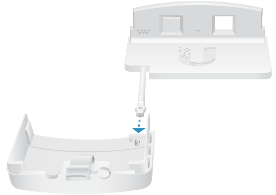
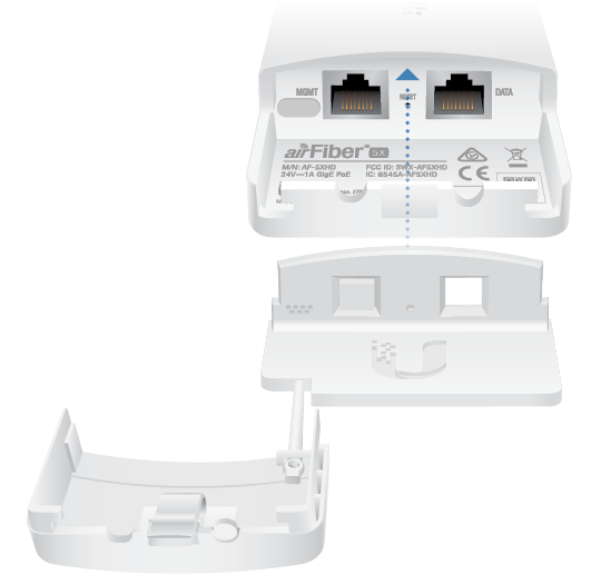
Upgrade for IP67 Compliance
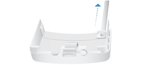
| Note: Do not damage or remove the post on the Port Cover. |
|---|
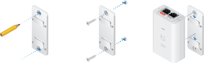
Hardware Installation
Installing the Ground Wire
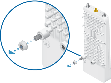
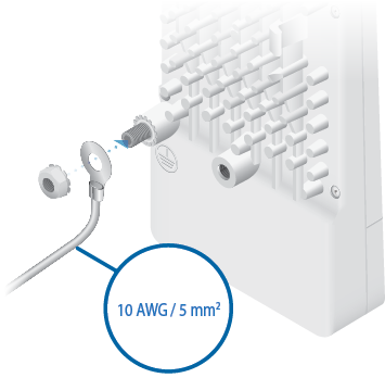
- At the installation site, secure the other end of the ground wire to a grounded mast, pole, tower, or grounding bar.
| WARNING: Failure to properly ground your airFiber radio will void your warranty. |
|---|
| Note: The ground wire should be as short as possible and no longer than one meter in length. |
|---|
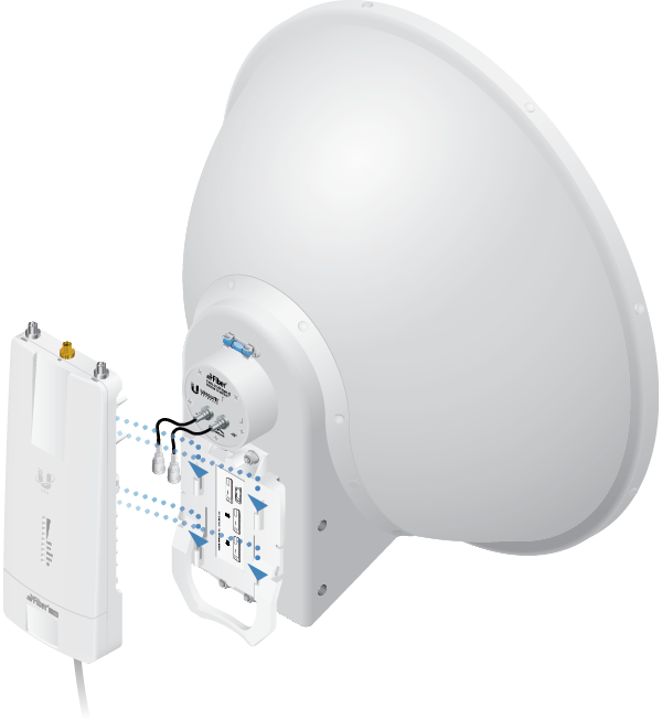
Mount to an airFiber X Antenna
|
|
Note: To mount the AF-5XHD to a RocketDish using the included Universal Bracket, see the Mount to a RocketDish Antenna section. |
|---|
The airFiber X antenna AF-5G23-S45 is shown in this section:
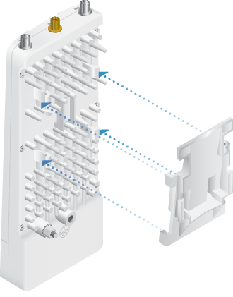
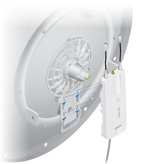
Mount to a RocketDish Antenna
|
|
Note: If you are mounting the AF-5XHD on a RocketDish equipped with the AF-5G-OMT-S45 Conversion Kit, the Universal Bracket is not needed. Refer instead to the Mount to an airFiber X Antenna section for instructions. |
|---|
The RocketDish RD-5G30 antenna is shown in this section:
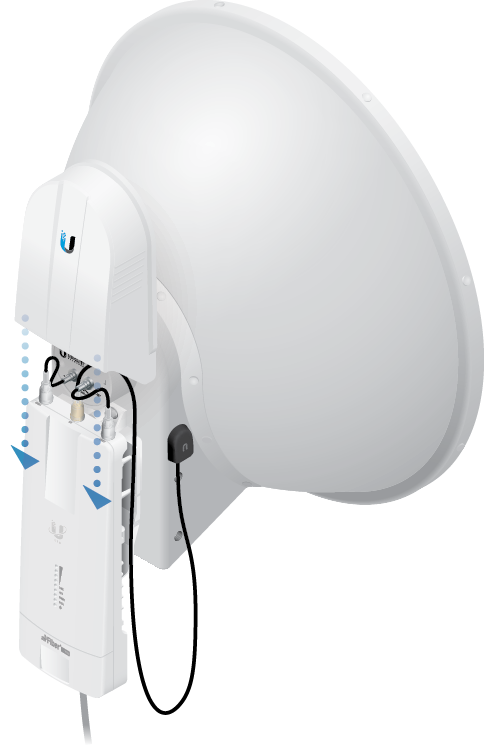
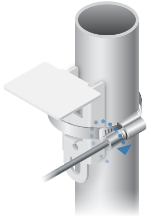
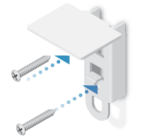
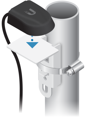
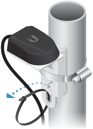
Mount the External GPS Antenna
Locate a mounting point that has a clear view to the sky, and is above and as far away as possible from the AF-5XHD.
OR
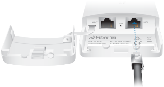
Connecting Power over Ethernet
OR
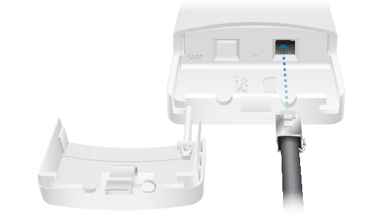
| Note: If the IP67 Upgrade Kit is installed, first apply dielectric grease to the cable connector and port. |
|---|
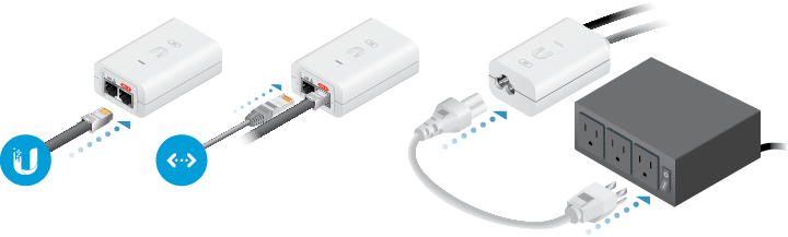
| WARNING: Use only the included adapter, model POE-24V-5X-HD. Failure to do so can damage the unit and void the product warranty. |
|---|
Optional
Surge Protection
For added protection, install two surge suppressors, such as the Ubiquiti Ethernet Surge Protector, model ETH-SP, at the end of each link. Install the first surge protector within one meter of the airFiber Data port, and install the second surge protector at the ingress point of the location housing the wired network equipment.
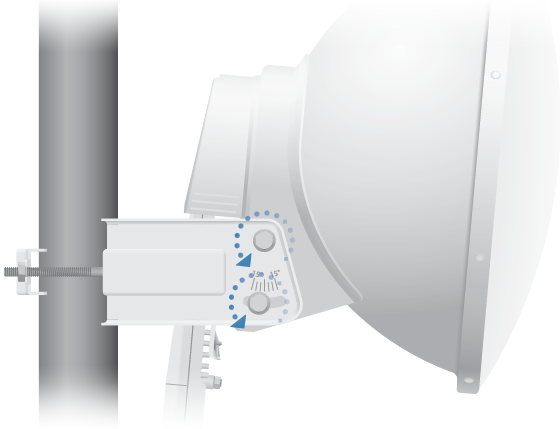
Alignment
Tips
- To accurately align the airFiber radios for best performance, you MUST align only one end of the link at a time.
- You may need to use additional hardware to compensate for issues such as the improper orientation of a mounting pole or significant elevation differences between airFiber radios.
Establishing a Link
Adjust the positions of the Master and the Slave to establish a link. The following section features the airFiber X antenna, AF-5G23-S45:
|
|
Note: The Master must be aimed first at the Slave because the Slave does not transmit any RF signal until it detects transmissions from the Master. |
|---|
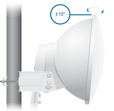
- Master Visually aim the Master at the Slave. To adjust the Master’s position, adjust the azimuth and the elevation.
Adjust the azimuth:
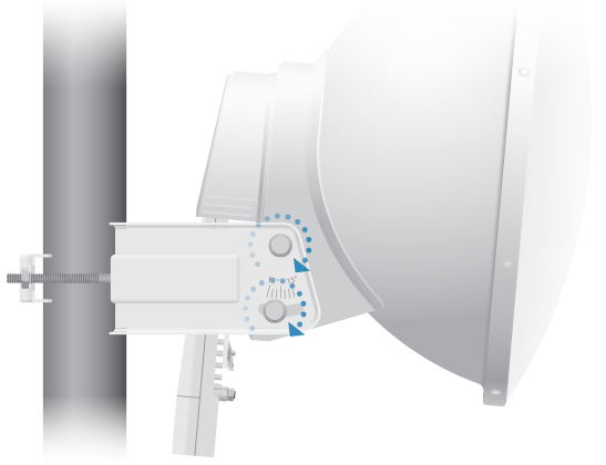
- Slave Visually aim the Slave at the Master. To adjust the Slave’s position, adjust the azimuth and elevation as described in step 1.
- Check to see if a link is established. Ensure that the Link LED is solidly lit green and the Signal LEDs of the Slave are displaying signal levels.
- Slave Aim the Slave at the Master to achieve the strongest signal level on the Master.
- Master Aim the Master at the Slave to achieve the strongest signal level on the Slave.
- Repeat steps 4 and 5 until you achieve an optimal link, with all four Signal LEDs solidly lit. This ensures the best possible data rate between the airFiber radios.
- Lock the alignment on both airFiber antennas by tightening all the nuts and bolts.
- Observe the Signal LEDs of each airFiber radio to ensure that the values remain constant while tightening the nuts and bolts. If any LED value changes during the locking process, loosen the nuts and bolts, finalize the alignment of each airFiber antenna again, and retighten the nuts and bolts.
| Note: Do NOT make simultaneous adjustments on the Master and Slave. |
|---|

| Note: Refer to the Signal LEDs section for details on the signal values. |
|---|
| Note: Maximum signal strength can best be achieved by iteratively sweeping through both azimuth and elevation. |
|---|
Installer Compliance Responsibility
Devices must be professionally installed and it is the professional installer’s responsibility to make sure the device is operated within local country regulatory requirements.
Antenna
Select your antenna from the list. If Auto Output Power is enabled, transmit output power is automatically adjusted to comply with the regulations of the applicable country. For a Custom antenna, Antenna Gain is entered manually. Note the requirements and antenna types listed below.
Cable Loss (When applicable)
Enter the cable loss in dB. Output power is adjusted to compensate for loss between the radio and the antenna.
Certified Antenna Types
This radio transmitter FCC ID: SWX-AF5XHD / IC: 6545A-AF5XHD has been approved by FCC / ISED Canada to operate with the antenna types listed below with the maximum permissible gain for each antenna type indicated. Antenna types not included in this list or having a gain greater than the maximum gain indicated for that type, are strictly prohibited for use with this device.
|
Antenna |
Frequency |
Gain |
|---|---|---|
|
Dish |
5 GHz |
34 dBi |
Specifications
|
AF-5XHD |
|
|
Dimensions |
224 x 82 x 48 mm (8.82 x 3.23 x 1.89") |
|---|---|
|
Weight |
0.35 kg (12.3 oz) |
|
RF Connectors |
(2) RP-SMA Weatherproof (CH0, CH1) (1) SMA Weatherproof (GPS) |
|
GPS Antenna |
External, Magnetic Base |
|
Power Supply |
24V, 1A PoE Gigabit Adapter (Included) |
|
Power Method |
Passive Power over Ethernet |
|
Supported Voltage Range |
+18 to +54VDC1 |
|
Max. Power Consumption |
6-12W2 |
|
Networking Interface |
|
| Data Port | (1) 10/100/1000 Ethernet Port |
| Management Port | (1) 10/100/1000 Ethernet Port Bluetooth v4.0 |
|
Mounting |
airFiber X Mount (Rocket Mount Compatible) GPS Pole Mount (Included) |
|
Operating Temperature |
-40 to 55° C (-40 to 131° F) |
|
Weatherproofing |
IP673 |
|
Certifications |
CE, FCC, IC |
1 Full range depends on Ethernet cable length.
2 Varies with firmware load and operational mode.
3 After installation of IP67 Upgrade Kit (included).
|
System |
|
|
Maximum Throughput |
1.34 Gbps1, 2 |
|---|---|
|
Encryption |
256-bit AES |
|
OS |
airOS LTU |
|
Wireless Modes |
Master/Slave |
1 May vary depending on environmental conditions.
2 Assuming 4096QAM (requires firmware version 1.1.2 or above).
|
Radio |
|
|
Max. Conducted TX Power |
29 dBm* |
|---|---|
|
Frequency Accuracy |
< 2 ppm |
|
Channel Bandwidth |
10/20/30/40/50/60/80/100 MHz Selectable |
|
Operating Frequency (MHz) |
||
|
Worldwide |
4800 - 6200* |
|
|---|---|---|
|
US/CA |
U-NII-1 | 5150 - 5250 |
|
U-NII-2A | 5250 - 5350 |
|
|
U-NII-2C | 5470 - 5725 |
|
|
U-NII-3 | 5725 - 5850 |
|
* Depends on regulatory region.
|
Bluetooth LE Management Radio (MHz) |
|
|
Worldwide |
2400 - 2483.5 |
|---|---|