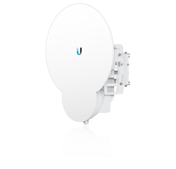
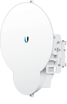
Package Contents
 |
|---|
| airFiber AF-24HD |
 |
|---|
| Pole Mount Bracket |
 |
|---|
| Pole Clamps (Qty. 2) |
 |
|---|
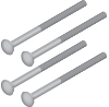
| Carriage Bolts (Qty. 4) |
 |
|---|
| Flat Washers (Qty. 4) |
 |
|---|
| Split Lock Washers (Qty. 4) |
 |
|---|
| Hex Nuts (Qty. 4) |
 |
|---|
| Metal Strap |
 |
|---|
| GPS Antenna Mount |
 |
|---|
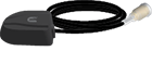
| External GPS Antenna |
 |
|---|
| Zip Ties (Qty. 3) |
 |
|---|
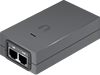
| Gigabit PoE Adapter (50V, 1.2A) |
 |
|---|
| Power Cord |
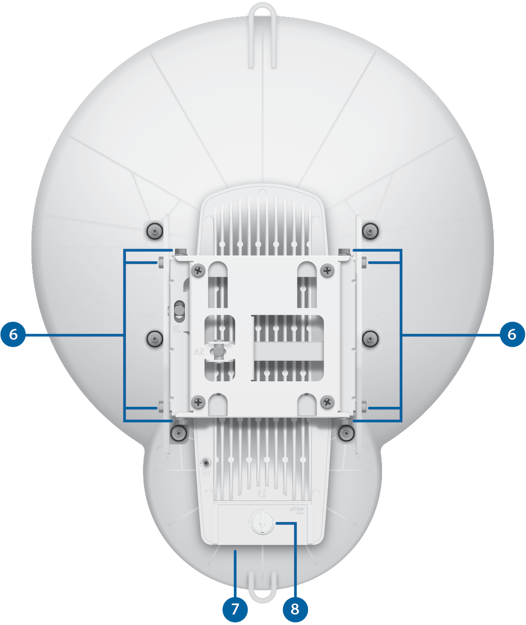
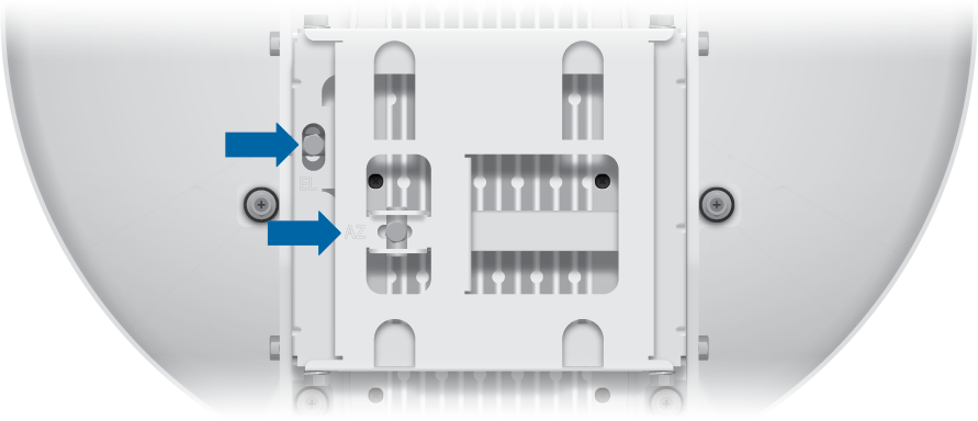
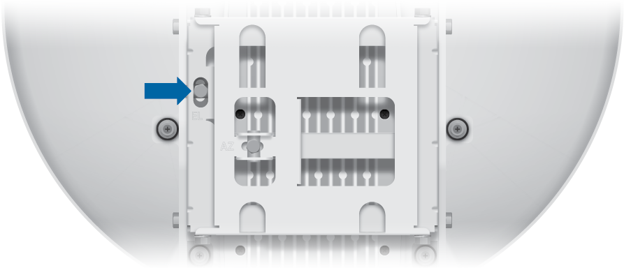
Hardware Overview
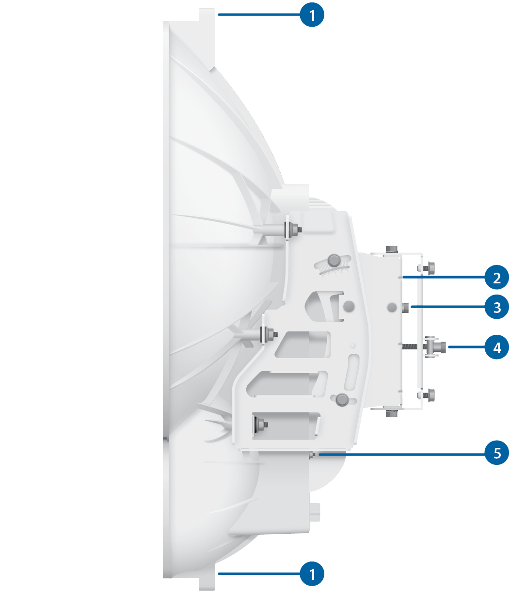
 Alignment Bracket |
|---|
 Elevation Adjustment |
 Azimuth Adjustment |
 Ground Bonding Point |
 Lock Bolts |

Lanyard Loops |
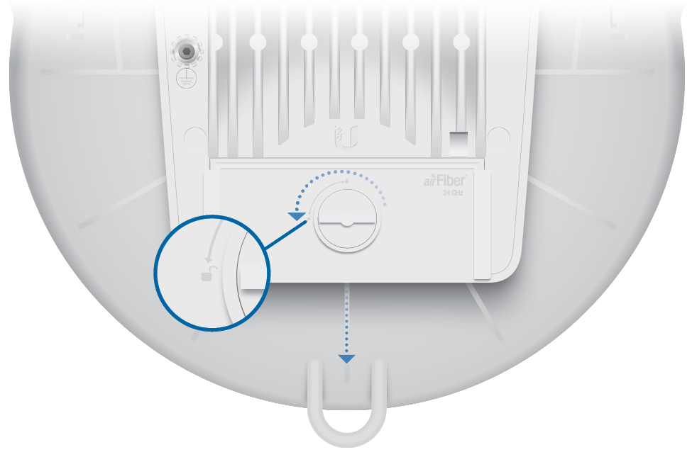
 Port Cover |
 Cover Lock |
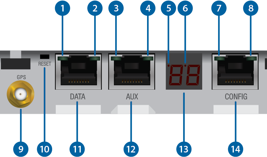
LEDs, Ports, and Display
|
Speed LED (Data Port) |
||||||||
|---|---|---|---|---|---|---|---|---|
Off |
10/100 Mbps |
|||||||
On |
1000 Mbps |
|||||||
|
Link/Activity LED (Data Port) |
||||||||
Off |
No Ethernet Link |
|||||||
On |
Ethernet Link Established |
|||||||
Random Flashing |
Ethernet Activity |
|||||||
|
GPS LED (Auxiliary Port) |
||||||||
Off |
No GPS Synchronization |
|||||||
On |
Operational (Strong Signal) |
|||||||
Normal Flash* |
Operational (Weak Signal) |
|||||||
|
Modulation LED (Auxiliary Port) |
||||||||
Off |
¼x or 1x (QPSK SISO) |
|||||||
Short Flash* |
2x (QPSK MIMO) |
|||||||
Normal Flash* |
4x (16QAM MIMO) |
|||||||
Long Flash* |
6x (64QAM MIMO) |
|||||||
On |
8x (256QAM MIMO) |
|||||||
|
Master/Slave LED |
||||||||
Off |
Slave Mode |
|||||||
On |
Master Mode |
|||||||
|
RF Link Status LED |
||||||||
Off |
RF Off |
|||||||
Short Flash* |
Syncing |
|||||||
Normal Flash* |
Beaconing |
|||||||
Long Flash* |
Registering |
|||||||
On |
Operational |
|||||||
|
Speed LED (Configuration Port) |
||||||||
Off |
10 Mbps |
|||||||
On |
100 Mbps |
|||||||
|
Link/Activity LED (Configuration Port) |
||||||||
Off |
No Ethernet Link |
|||||||
On |
Ethernet Link Established |
|||||||
Random Flashing |
Ethernet Activity |
|||||||

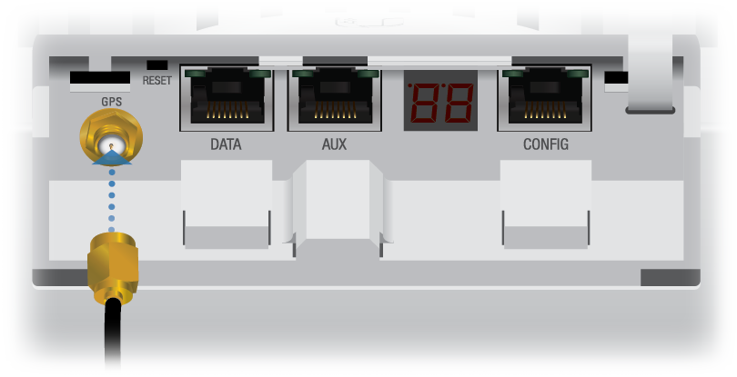
GPS Port |
||||||||
Connect the External GPS Antenna to this SMA connector. |
||||||||

Reset Button |
||||||||
To reset to factory defaults, press and hold the Reset button for more than five seconds while the unit is powered on. |
||||||||

Data Port |
||||||||
10/100/1000 Mbps port handles all user traffic. |
||||||||

Auxiliary Port |
||||||||
Port for audio tone aiming. |
||||||||

LED Display |
||||||||
Digital display used for power, status, and mode information.
|
||||||||

Configuration Port |
||||||||
10/100 Mbps, secured port for configuration. By default, this is the only port that can monitor, configure, and/or update firmware. |
||||||||
* Short Flash (1:3 on/off cycle)
Normal Flash (1:1 on/off cycle)
Long Flash (3:1 on/off cycle)
Installation Requirements
- 17 mm wrench
- 13 mm socket wrench or driver
- Clear line of sight between airFiber radios
- Clear view of the sky for proper GPS operation
- Mounting location with < 0.5° displacement due to twist and sway under wind loading
- Mounting point:
- At least 1 meter below the highest point on the structure
- For tower installations, at least 3 meters below the top of the tower
- Ground wires – min. 8 AWG (10 mm2) and max. length: 1 meter. As a safety precaution, ground the airFiber radios to grounded masts, poles, towers, or grounding bars.

WARNING: Failure to properly ground your airFiber units will void your warranty.
- (Recommended) 2 Outdoor Gigabit PoE surge protectors – Ubiquiti® Ethernet Surge Protector, model ETH-SP-G2.

Note: For guidelines about grounding and lightning protection, follow your local electrical regulatory codes.
- Outdoor, shielded Category 5e (or above) cabling and shielded RJ-45 connectors should be used for all wired Ethernet connections. Category 6 is required for installations with long cable runs (up to 100 m).
We recommend that you protect your networks from harmful outdoor environments and destructive ESD events with industrial-grade, shielded Ethernet cable from Ubiquiti. For more details, visit ui.com/toughcable
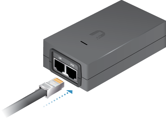
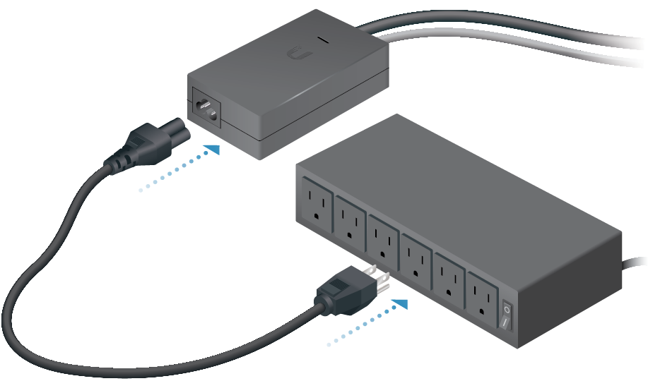
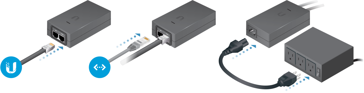
Connecting Power over Ethernet

airFiber Configuration
The instructions in this section explain how to access the airFiber Configuration Interface and configure the following settings:
- Wireless Mode Configure one airFiber AF-24HD as the Master and the other as the Slave.
- Duplex The airFiber AF-24HD supports both half-duplex and full-duplex operation. Half-duplex operation provides more frequency planning options at the cost of higher latency and throughput. Full-duplex operation provides the highest throughput and lowest latency; however, you have fewer frequency management options.
- Half Duplex (default) The TX and RX Frequencies can be the same or different to suit local interference.
- Full Duplex The TX and RX Frequencies should be different.
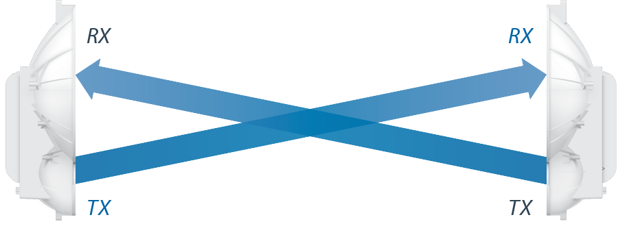
Half-Duplex Diagram
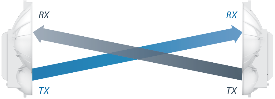
Full-Duplex Diagram
- TX and RX Frequencies The TX Frequency on the Master must match the RX Frequency on the Slave, and vice versa.
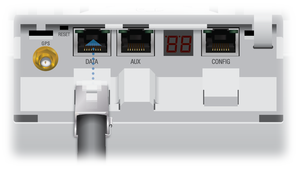
- Connect an Ethernet cable from your computer to the CONFIG port on the airFiber AF-24HD.
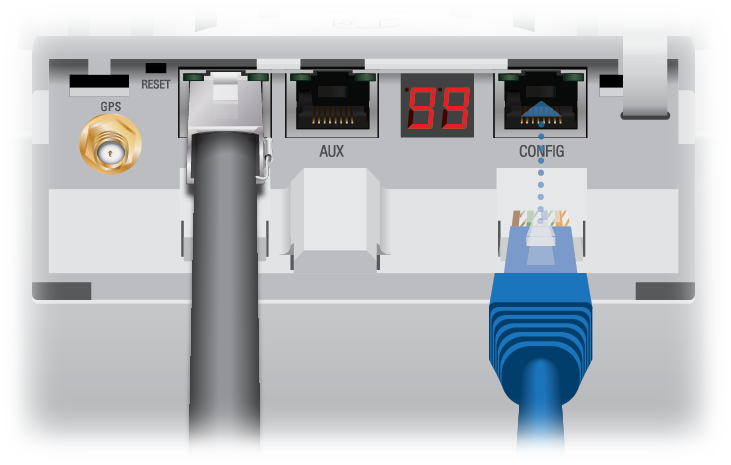
- Configure the Ethernet adapter on your computer with a static IP address on the 192.168.1.x subnet (for example, 192.168.1.100).
- Launch your web browser. Type http://192.168.1.20 in the address field and press enter (PC) or return (Mac).

- The login screen will appear. Enter ubnt in the Username and Password fields. Select your Country and Language. You must agree to the Terms of Use to use the product. Click Login.
Note: U.S. product versions are locked to the U.S. Country Code to ensure compliance with FCC regulations.
- Click the Wireless tab.
- Enter the Basic Wireless Settings:
- For one airFiber AF-24HD, select Master from the Wireless Mode drop-down. For the other airFiber AF-24HD, keep the default, Slave.
- Enter a name in the Link Name field. This should be the same on both the Master and the Slave.
- For the Duplex drop-down:
- Half Duplex The default mode. The TX and RX Frequencies can be the same or different to suit local interference.
- Full Duplex The TX and RX Frequencies should be different.
- Select a TX Frequency. This must match the RX Frequency of your other airFiber AF-24HD.
- Select a RX Frequency. This must match the TX Frequency of your other airFiber AF-24HD.
- If needed, change the Output Power, Maximum Modulation Rate, and/or RX Gain settings.
- Configure the Wireless Security:
- Select the AES Key Type, HEX or ASCII.
- For the Key field:
- HEX Enter 16 bytes (eight, 16-bit HEX values: 0-9, A-F, or a-f). You can omit zeroes and use colons, similar to the
IPv6 format.Note: The airFiber Configuration Interface supports IPv6 formats excluding dotted quad and "::" (double-colon) notation.
- ASCII Enter a combination of alphanumeric characters (0-9, A-Z, or a-z).
- HEX Enter 16 bytes (eight, 16-bit HEX values: 0-9, A-F, or a-f). You can omit zeroes and use colons, similar to the
- Click Change and then click Apply.
- In-Band Management is enabled by default, so each airFiber radio must have a unique IP Address. (If the airFiber radios use the same IP Address, then you may lose access to the airFiber radios via the DATA ports.) To change the network settings:
- Click the Network tab.
- Change the IP Address, Netmask, and other settings to make them compatible with your network.
- Click Change and then click Apply.
Repeat the instructions in the airFiber Configuration section on your other airFiber radio. After you have configured the airFiber radios, disconnect them and move them to your installation site.
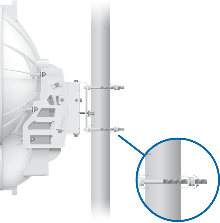
Hardware Installation
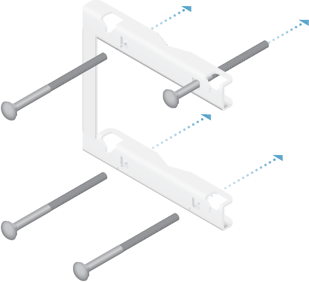
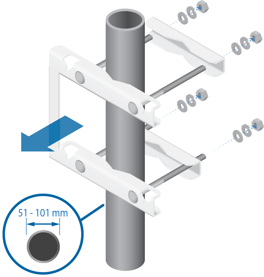
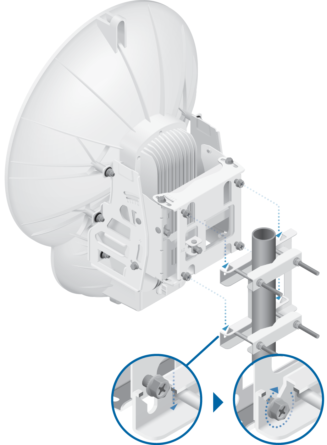
Note: Orient the Pole Mount Bracket around the pole so it is aimed in the direction of the other airFiber AF-24HD.
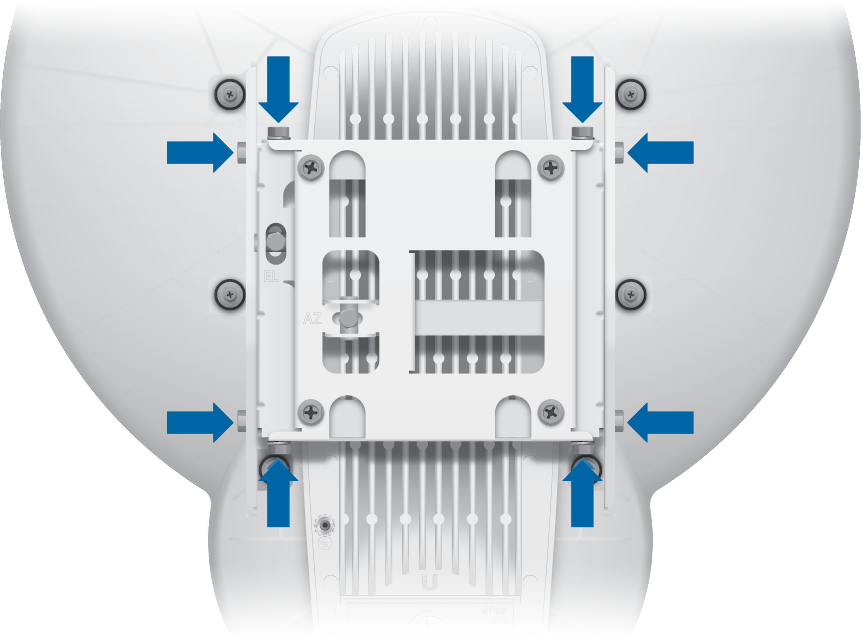
Note: Loosen, but do NOT remove the eight Lock Bolts located on the Alignment Bracket.
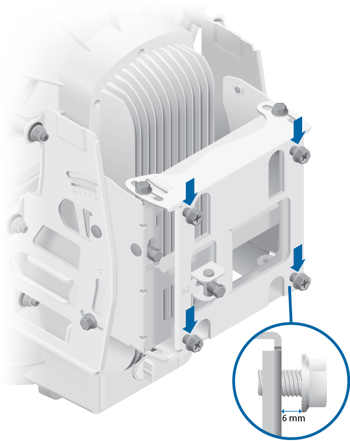
WARNING: To prevent injury, ensure that all four screws are seated and fully tightened.
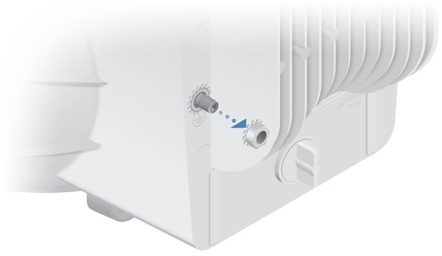
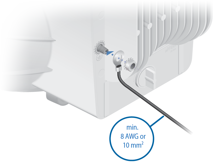
- Secure the other end of the ground wire to a grounded mast, pole, tower, or grounding bar.
|
|
WARNING: Failure to properly ground your airFiber units will void your warranty. |
|---|
|
|
Note: The ground wire should be as short as possible and no longer than one meter in length. |
|---|
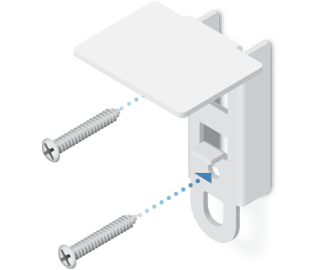
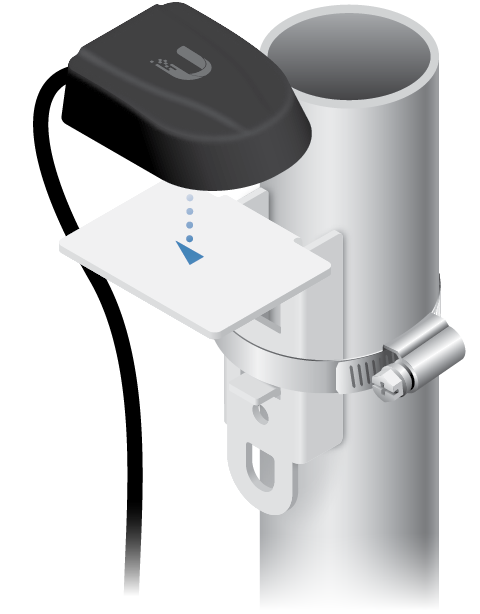
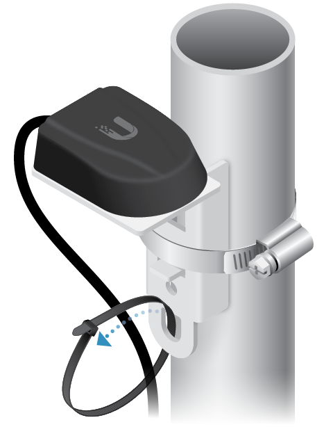
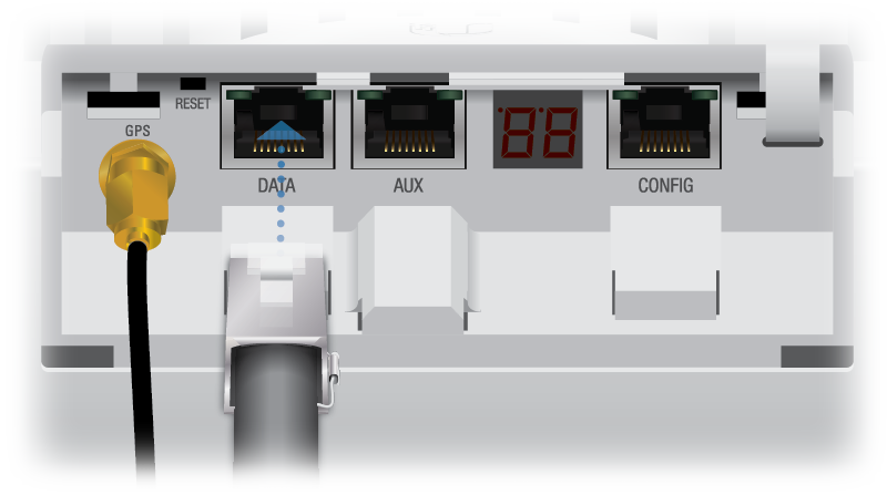
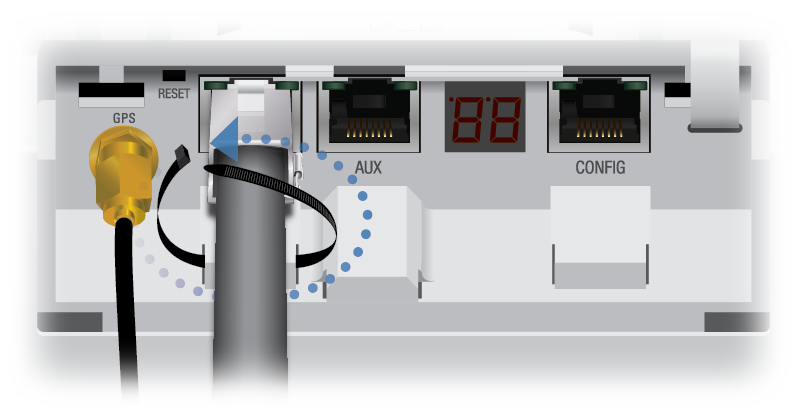
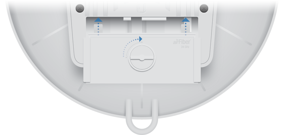
Connecting the GPS Antenna
Locate a mounting point for the External GPS Antenna that has a clear view to the sky, and is above and as far away as possible from the AF-24HD.
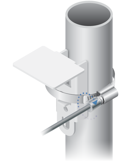
OR
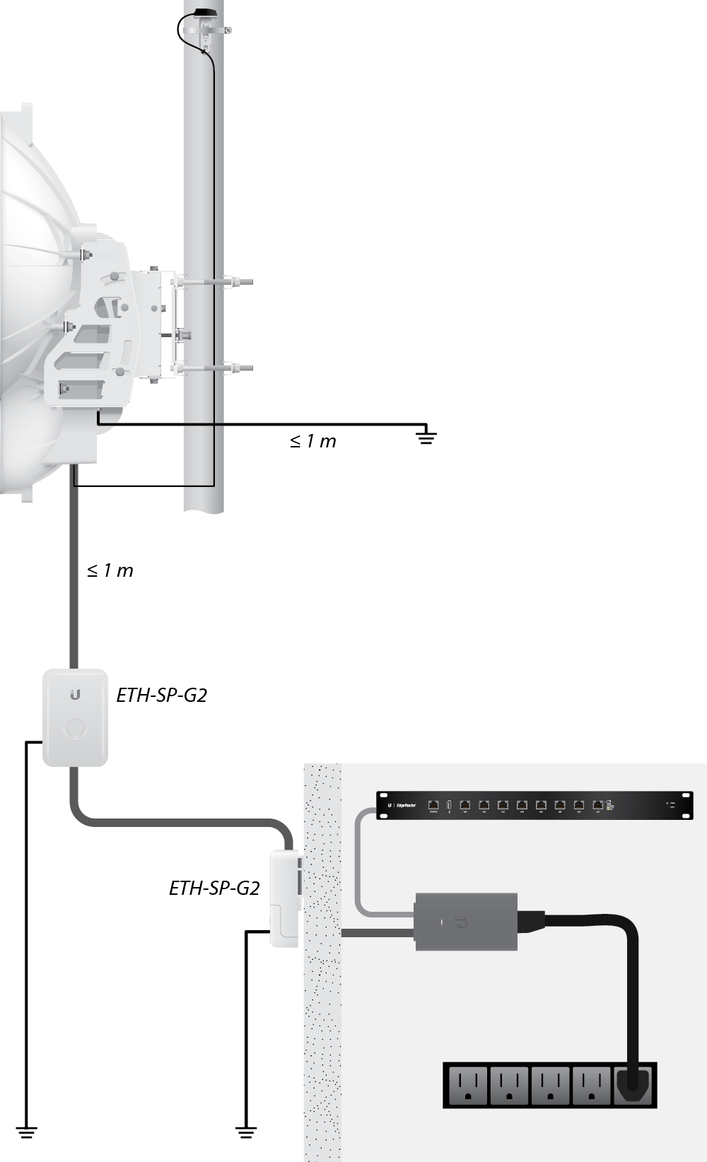
Connecting Ethernet
|
|
Note: For added protection, we recommend installing two surge surpressors, such as the Ubiquiti Ethernet Surge Protector, model ETH-SP-G2. Install the first surge protector within one meter of the airFiber DATA port, and install the second surge protector at the ingress point of the location housing the wired network equipment. |
|---|
Below is a diagram of a finished installation with recommended surge protectors installed.
Alignment
Tips
- Fine-tuning is best achieved by a pair of installers with a dedicated, two-way communication link: one installer makes adjustments on one airFiber radio while the other installer reports the received signal level at the other airFiber radio. Fine-tuning (see "Fine-Tuning the Link") is necessary because the main lobe of the receiver is narrower than that of the transmitter, in both azimuth and elevation.
- To accurately align the airFiber radios for best performance, you MUST align only one end of the link at a time.
- For more convenient alignment, you may consider using long-range scopes (not included) temporarily attached to your airFiber radios.
- You may need to use additional hardware to compensate for issues such as the improper orientation of a mounting pole or significant elevation differences between the airFiber radios.
Establishing a Preliminary Link
Adjust the positions of the Master and the Slave to establish a preliminary link. This requires the Master and Slave to be within a few degrees of the line of sight between the airFiber radios.
|
|
Note: The Master must be aimed first at the Slave because the Slave does not transmit any RF signal until it detects transmissions from the Master. |
|---|
- For the Master and Slave, ensure the eight Lock Bolts on the Alignment Bracket are sufficiently loose by spinning each washer by hand.
WARNING: All Lock Bolts MUST be loose to avoid damage to the airFiber housing.
- For the Master and Slave, ensure the Azimuth (AZ) and Elevation (EL) Adjustment Bolts are in the middle of their adjustment ranges.
- Master Aim the Master at the Slave. If necessary, adjust the Master's position on the pole:
- Loosen the Hex Nuts.
- Adjust the Pole Mount Bracket and Pole Clamps.
- Tighten the Hex Nuts.
- Loosen the Hex Nuts.
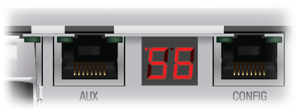
- Slave Aim the Slave at the Master to achieve the strongest received signal level on the Slave's numeric LED Display, which is located next to the CONFIG port. If necessary, adjust the Slave's position on the pole.
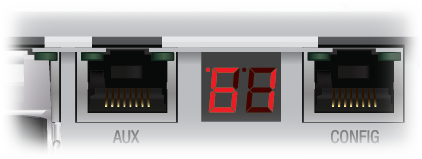
Note: Values on the LED Display are displayed in negative (-) dBm. For example, 61 represents -61 dBm, which is stronger than -72 dBm.
- Master Adjust the azimuth and elevation of the Master until the strongest received signal level is displayed on the LED Display of the Master.
- Sweep the Azimuth (AZ) Adjustment Bolt of the Master through its adjustment range.
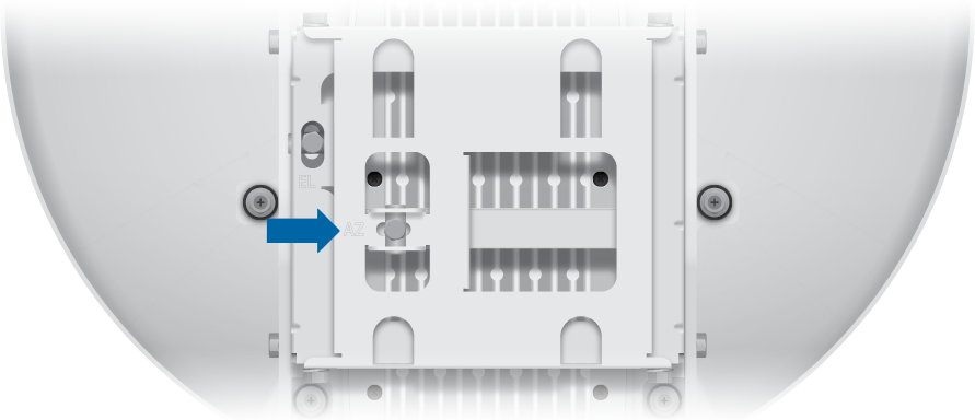
- Sweep the Elevation (EL) Adjustment Bolt of the Master through its adjustment range.
- Sweep the Azimuth (AZ) Adjustment Bolt of the Master through its adjustment range.
|
|
Note: If the LED Display indicates an overload condition |
|---|
 , refer to the following section, Adjusting RX Gain.
Adjusting RX Gain
Access airOS® and click the Wireless tab to select the appropriate gain for your RX antenna: High (default) or Low. If the link is very short or being tested, select Low, so your signal does not get distorted.
|
|
Note: Minimum link distance is approximately 100 m (328 ft). |
|---|
For links between 100 m (328 ft) and 800 m (2,625 ft):
- Target -40 dBm.
- Decrease RX Gain to overcome overload condition (
 ).
). - For short ranges or strong signal conditions, adjust the power to be 3-5 dB below overload condition ( ).
- Decrease RX Gain first.
- Never mitigate overload condition ( ) by misaligning antennas.
Link Distance | RX Gain Setting | Approximate |
|---|---|---|
d > 1 km | High | > 25 dBm |
0.5 km < d < 1 km | Low | 19-25 dBm |
0.25 km < d < 0.5 km | Low | 12-18 dBm |
0.1 km < d < 0.25 km | Low | 3-11 dBm |
Fine-Tuning the Link
The Azimuth (AZ) and Elevation (EL) Adjustment Bolts of the Alignment Bracket adjust the azimuth and elevation within a range of ±10°. For accurate alignment, make adjustments on one end of the link while the other installer reports the received signal level at the other end of the link. Do NOT make simultaneous adjustments on the Master and Slave.
- Slave Adjust the azimuth and elevation of the Slave until the other installer sees the strongest received signal level displayed on the LED Display of the Master.
- Master Adjust the azimuth and elevation of the Master until the other installer sees the strongest received signal level displayed on the LED Display of the Slave.
- Repeat steps 1 and 2 until you achieve a symmetric link, with the received signal levels within 1 dB of each other. This ensures the best possible data rate between the airFiber radios.
- Lock the alignment on both airFiber radios by tightening all eight Lock Bolts on the Alignment Bracket.
- Observe the LED Display of each airFiber AF-24HD to ensure that the value remains constant while tightening the Lock Bolts. If the LED value changes during the locking process, loosen the Lock Bolts, finalize the alignment of each airFiber AF-24HD again, and retighten the Lock Bolts.
There are three methods for determining the received signal level:
- LED Display (described above)
- airFiber Configuration Interface
- Audio tone (optional equipment required)
Refer to the airFiber AF-24HD User Guide for instructions on the airFiber Configuration Interface and audio tone methods. The User Guide is available at: ui.com/download/airfiber
Installer Compliance Responsibility
Devices must be professionally installed and it is the professional installer's responsibility to make sure the device is operated within local country regulatory requirements.
The Frequencies and Output Power fields are provided to the professional installer to assist in meeting regulatory requirements.
Specifications
|
airFiber AF-24HD |
|
|
Dimensions |
593 x 768 x 370 mm (23.35 x 30.24 x 14.57") |
|---|---|
|
Weight |
17.3 kg (38.14 lb) |
|
Operating Frequency |
24.05 – 24.25 GHz |
|
GPS |
GPS Clock Synchronization |
|
EIRP |
~33 dBm (FCC/IC), ~20 dBm (CE) |
|
Frequency Accuracy |
± 2.5 ppm without GPS Synchronization |
|
Channel Bandwidth |
100 MHz |
|
Max. Power Consumption |
< 50W |
|
Power Supply |
50V, 1.2A PoE Gigabit Adapter (Included) |
|
Power Method |
Passive Power over Ethernet (42-58VDC) |
|
Certifications |
CE, FCC, IC |
|
Mounting |
Pole Mount Kit (Included) |
|
Operating Temperature |
-40 to 55° C (-40 to 131° F) |
|
Integrated Split Antenna |
|
|
TX Gain |
33 dBi |
|
RX Gain |
40 dBi |
|
Beamwidth |
< 3.5° |
|
Front-to-Back Ratio |
70 dB |
|
Polarity |
Dual-Slant Polarization |
|
Cross-Polarity Isolation |
> 28 dB |
|
Networking Interface |
|
|
Data Port |
(1) 10/100/1000 Ethernet Port |
|
Configuration Port |
(1) 10/100 Ethernet Port |